3
Safety logic module FE201 (continued)
23 of 70
Hardware R2.2.8 11.98.02 en
3.3
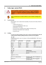
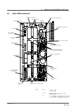
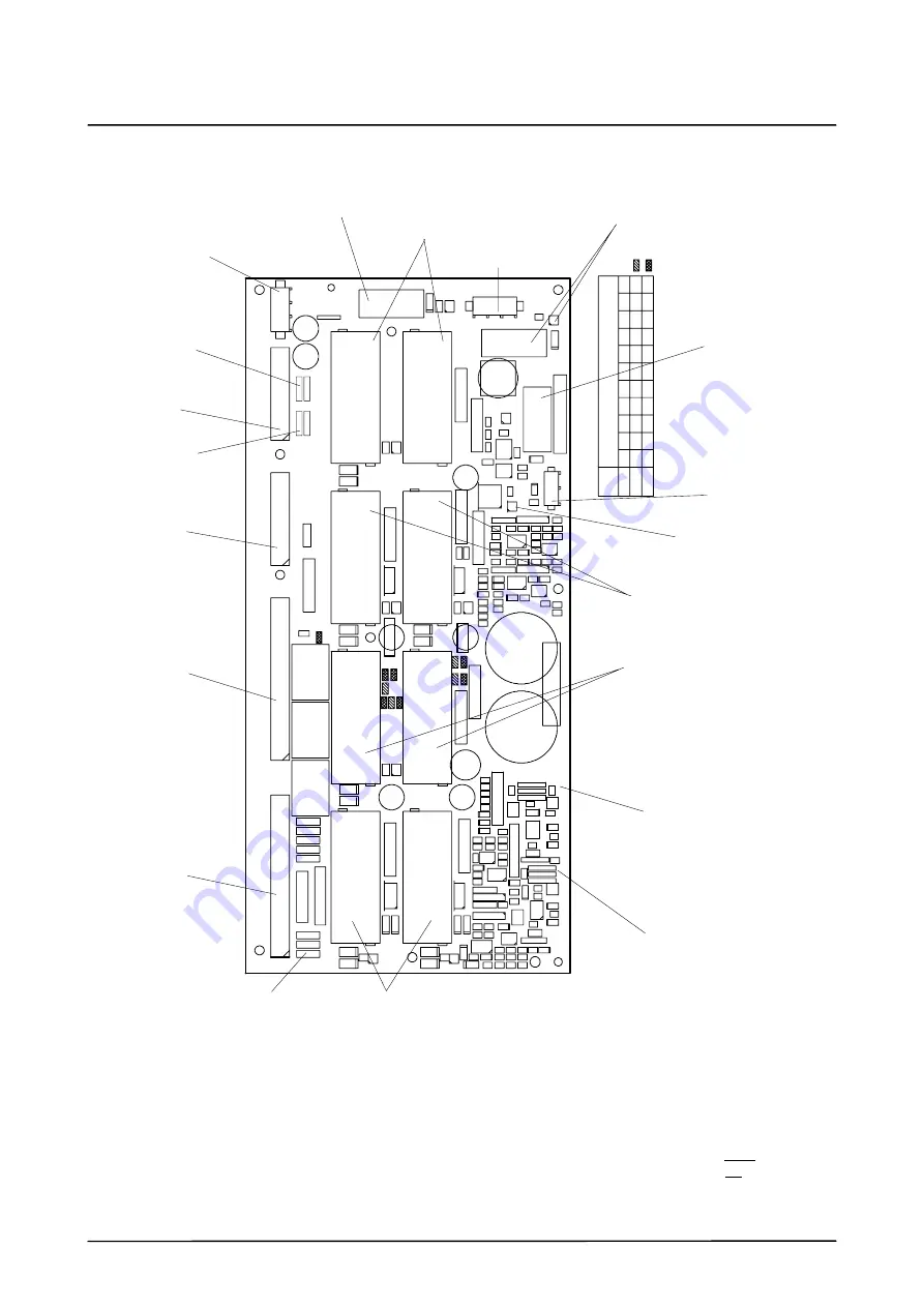
View FE201 version B
K7
K8
K5
K6
X9
21
X9
23
L1
1
L12
L10
K4
K3
K1
K2
X9
25
X9
24
K9
F1
1
K1
3
K1
4
C3
C8
C1
C1
4
C6
C1
1
C9
C1
2
Label
,c
om
ponent
si
de
X9
26
Co
nf
ig
ur
at
io
n
of
th
e
O
R
re
si
st
or
s
FE
201
VFE2
01
X
X
XX
X
X
X
X
X
XX
R4
5
R4
6
R4
7
R4
8
R4
9
R5
0
R5
1
R5
2
R5
3
R5
4
R5
5
Label
,
so
ld
er
in
g
si
de
R3
6
R3
5
R1
V6
1
R2
C1
0
R8
D1
U4
U1
U2
N1
N3
R2
4
R2
3
D4
X9
27
R2
9
R3
0
V2
8
D3
V3
9
Jumpers :
with 6 axes, closed
with > 6 axes, open
EMERGENCY STOP delay approx.1.3s, open
approx. 0.5s, closed
Pos. b: EMERGENCY STOP without path--oriented braking
Pos. a: EMERGENCY STOP with path--oriented braking
X7 -- X9
X1 -- X6
X10
”Drives ON” relay with LED
Voltage supply connector
DIP--FIX switch X10
DIP--FIX switches
FK connector PM...
FK connector MFC
FK connector
(Standard) interface X11
(VW) FE202
”EMERGENCY STOP” relays with LEDs
DIP--FIX switches
X1--X3
DIP--FIX switches
X4--X6
”Automatic” relays with LED
LED V39 main switch operation
Connector X927 main switch operation
”Safety” relays with LEDs
”Test” relays with LED
”27 V voltage monitoring” relay
a b
X9
22
Thermal fuses for
safety circuit
“Drives ON” relays of MFC with LED
FK connector PM...
for external axes (optional)
X7--X9
for basic axes
with LED
operator safety and enabling
Connector
interface
Содержание KR C1
Страница 1: ...Hardware R2 2 8 11 98 02 en 1 of 70 SOFTWARE KR C1 Hardware Release 2 2...
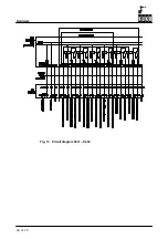
Страница 30: ...Hardware 30 of 70 Hardware R2 2 8 11 98 02 en Fig 13 Circuit diagram X931 X604...
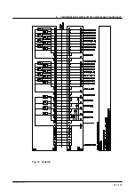
Страница 31: ...4 Individual axis switch off for external axes continued 31 of 70 Hardware R2 2 8 11 98 02 en Fig 14 Outputs...
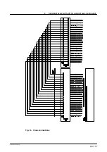
Страница 32: ...Hardware 32 of 70 Hardware R2 2 8 11 98 02 en Fig 15 Inputs...
Страница 34: ...Hardware 34 of 70 Hardware R2 2 8 11 98 02 en...
Страница 35: ...35 of 70 Hardware R2 2 8 11 98 02 en...
Страница 55: ...55 of 70 Hardware R2 2 8 11 98 02 en...


