background image

244

406388/F

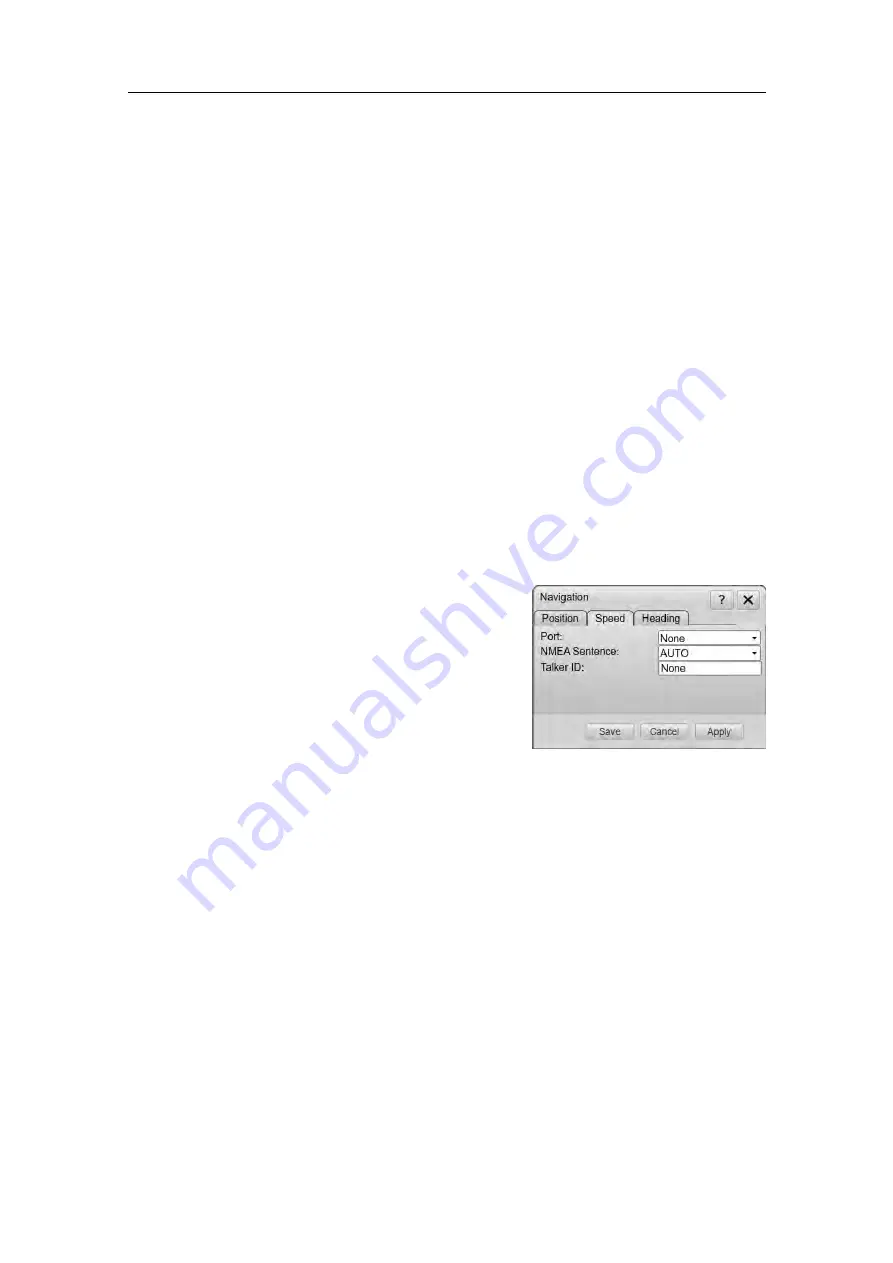
Talker ID

If you want to specify a dedicated Talker ID for the datagram format, it can be
defined here. Every NMEA datagram starts with a dollar ($) character. The "talker
identifier" (ID) with two characters follows immediately after the dollar character.
The Talker ID is followed by three characters that define the

type

of datagram.

The Talker ID identifies the system that

sends

the datagram. When no Talker ID

is defined, all identifiers are accepted.

Related topics

Navigation dialog box, page 242

Speed page

The parameters on the

Speed

page allows you to control the interface with external

speed sensors.

How to open

This dialog box is opened from the

Setup

menu.

Description

An external speed sensor is typically a global
positioning system (GPS) or a dedicated speed
log. The sensor is connected using a serial or local
area network (LAN) port on your Processor Unit.
The information from the speed sensors provides
the speed information on the TV80 top bar.

Details

Port

Select which serial or Ethernet port to use for this communication.

NMEA Sentence

Select which NMEA, third party or proprietary datagram format to be used for
the communication.

Auto

The TV80 will read all relevant datagrams. If the specified information is
provided to the system on more than one telegram format, a built-in priority
list will be used.

NMEA VHW

The NMEA VHW datagram contains the compass heading to which the vessel
points, and the speed of the vessel relative to the water.

NMEA VTG

Simrad TV80 Reference Manual

Содержание Simrad TV80

Страница 1: ...kongsberg com simrad Simrad TV80 REFERENCE MANUAL ...

Страница 2: ......

Страница 3: ...l also offers a thorough understanding of the various TV80 operational settings and adjustments The information in this manual is also available in the TV80 context sensitive On line help Additional end user documents related to the TV80 system can be found on our website This includes publications that are translated to other languages Selected publications are also provided on IETM Interactive E...

Страница 4: ...Improper use or maintenance may cause damage to the equipment and or injury to personnel You must be familiar with the contents of the appropriate manuals before attempting to operate or work on the equipment Kongsberg Maritime disclaims any responsibility for damage or injury caused by improper installation use or maintenance of the equipment Disclaimer Kongsberg Maritime AS endeavours to ensure ...

Страница 5: ...y 30 Presentation overview 32 Starting normal operation 34 Adjusting the screen resolution 34 Selecting menu language 35 Selecting measurement units 36 Obtaining and installing the software license 37 Setting up the interfaces to peripheral devices 39 Recording the data received from PX sensors 54 Recording the information received on serial ports 55 Setting up the TV80 Catch Monitoring Software f...

Страница 6: ...oosing factory default settings 86 Defining settings related to user preferences and individual customizing 88 Selecting menu language 88 Changing the colour palette skin used in the display presentations 89 Selecting measurement units 89 Selecting the location of the menu 90 Setting up the sensors alarms 91 Opening the context sensitive online help 92 Working with views and layouts 93 Selecting t...

Страница 7: ...Ethernet LAN port 128 Verifying communication with external sensors and systems 129 Verifying the communication with a navigation system GPS 130 Verifying the communication with the course gyro 131 Verifying the communication with speed log 132 Checking the data transfer on a serial line 134 Checking the sensor readings 135 Configuring catch monitoring sensors parameters and defining their measure...

Страница 8: ... sensors 162 Recording the information received on serial ports 163 Accessing the saved data files 164 Replaying data received on a serial COM port 165 Replaying PX sensors data received on an Ethernet port 165 Resetting the timer function in the catch sensors 167 Installing upgrading and removing the TV80 software 168 Installing the TV80 operating software 168 Checking the current software versio...

Страница 9: ...Designer module bottom bar description 205 Gauge shortcut menu 205 View shortcut menu 207 Load View dialog box 207 Edit View function 209 Designer module Functions and dialog boxes 210 Gauges dialog box 210 Edit Gauge dialog box 211 FUNCTIONS AND DIALOG BOXES 213 Main menu Functions and dialog boxes 214 User Settings dialog box 214 Operation menu Functions and dialog boxes 216 Operation function 2...

Страница 10: ...olour Scale 253 Range Marker function 254 Ping Ping Filter function 254 View shortcut menu Functions and dialog boxes 256 PX Sensors Configuration dialog boxes 257 PX Configurator first dialog box 258 Introduction to PX Sensors Configuration dialog boxes 259 PX MultiSensor Mk2 configuration dialog box 260 PX MultiCatch configuration dialog box 262 PX Universal configuration dialog box 263 PX Flow ...

Страница 11: ...7 SR15 Hydrophone Setup dialog box 308 OVERVIEW OF SENSORS CHANNELS AND FREQUEN CIES 309 OVERVIEW OF CATCH MONITORING MEASUREMENTS 312 DATAGRAM FORMATS 315 About NMEA and standard datagram formats 316 About the NMEA datagram formats 316 NMEA 317 NMEA sentence structure 317 Standard NMEA 0183 communication parameters 318 NMEA datagram formats 319 NMEA DBS datagram format 319 NMEA GGA datagram forma...

Страница 12: ...10 406388 F Simrad PSIMP F datagram format 330 Simrad PSIMP D1 datagram format 331 Simrad DBS datagram format 333 Simrad TV80 ...

Страница 13: ... to identify settings that will provide the best data at all times A careful study of the information in this manual is highly recommended preferably while exploring the functionality offered by the TV80 system We assume that you are familiar with the basic acoustic principles of sound in water We also expect that you have some experience with catch monitoring systems Use the Help button Installed...

Страница 14: ...trademarks of Kongsberg Maritime AS in Norway and other countries Windows is a registered trademark of Microsoft Corporation in the United States and other countries We want your feedback We always want to improve our products We also want our end user documentation to be comprehensive and relevant You can help Please provide comments suggestions or constructive criticism to any of our support off...

Страница 15: ...8 F 13 Introduction Topics Important page 14 System description page 15 Key features page 17 System diagram page 18 Main system units page 20 Network security page 24 Support information page 25 Introduction ...

Страница 16: ...80 for a long time we recommend that you also switch of the receiver unit s The sensor receiver is normally not fitted with an on off switch To power down you must disconnect the power cable If something breaks down If you believe that something has broken down contact your local dealer A list of all our dealers is provided on our website www kongsberg com simrad If you are unable to contact a dea...

Страница 17: ...stem can present data received from the following catch monitoring systems Simrad PI32 Simrad PI44 Simrad PI54 Simrad ITI Simrad FS70 Simrad PX Catch monitoring sensors The Simrad TV80 system can be connected and can also control the following receivers Simrad PI50 Receiver Unit Simrad PI60 Receiver Unit Simrad SR15 Receiver Unit Simrad SR70 Receiver Unit User configurable presentation of data Sev...

Страница 18: ...t show real time data from the catch monitoring sensors You can however define and configure your own set up of catch monitoring sensors for a later use You can add an SR Replayer to replay some previously recorded PX sensors data Next to the software version in the bottom bar you can see if no license is installed Purse Seine License You can set up a purse seine gear and add and configure all the...

Страница 19: ...Easy operation with intuitive user interface Flexible screen presentation Up to four simultaneous views on each screen Multiple monitors setup User settings define and save your own Built in spectrum analyser Stable data readings Menu system and user interface in many languages With the TV80 you can see the data from your TrawlEye sensor in true motion mode Related topics System description page 1...

Страница 20: ... the Processor Unit is made using a high speed Ethernet line E Hydrophone Interface and Splitter F Hydrophone G Serial communication with Simrad ITI and or FS70 systems The TV80 system is a software program The Processor Unit is connected to one or more receiver units Each receiver can read the information provided by the sensors you have placed on your gear The TV80 can also communicate with othe...

Страница 21: ...page 15 Main system units page 20 Display description page 20 Computer description page 20 PI50 60 Receiver Unit page 21 SR15 Receiver Unit page 21 SR70 Receiver Unit page 22 Hydrophone page 23 Hydrophone Interface and Splitter page 23 Introduction ...

Страница 22: ...al software and offers the user interface that allows you to control the TV80 Furthermore it offers a number of serial and Ethernet lines for communication with external devices In this publication the computer can also be referred to as the Processor Unit and vice versa The computer must meet the operating system requirements provided by Microsoft The computer must also provide the necessary inte...

Страница 23: ...its page 20 System diagram page 18 SR15 Receiver Unit The SR15 Catch Monitoring Receiver comprises a rugged box providing all necessary receiver electronics The SR15 has one hydrophone input plug A receiver is used in catch monitoring systems to receive the information from the wireless sensors mounted on the gear and send it to the computer where the TV80 program is installed The communication be...

Страница 24: ...MultiCatch PX Flow PX TrawlEye The SR70 operates on 110 to 230 VAC Depending on your fishing requirements you may need to install more than one hydrophone to receive the information from the catch sensors This allows simultaneous reception without any need of switches or splitters The receiver is designed for low noise It can handle input signals spanning a very large instantaneous dynamic amplitu...

Страница 25: ...to provide the system with optimal reception from the sensors on a bottom or pelagic trawl This specific beam pattern is especially suited for trawling Portable hydrophone A portable hydrophone is also available It is designed as a temporary solution until a fixed hydrophone can be installed at the vessel s next planned dry docking It has an omnidirectional beam and a 50 meter integrated cable The...

Страница 26: ...Maritime has no information regarding the complete system installation on any vessel Systems provided by Kongsberg Maritime are regarded as stand alone offline systems They are stand alone even though they may be connected to a network for sensor interfaces and or data distribution Note No network safety applications are installed on Kongsberg Maritime computers The computers are therefore not pro...

Страница 27: ...d com Spain Company name Kongsberg Maritime Spain S L U Address Partida Atalayes 20 03570 Villajoyosa Spain Telephone 34 966 810 149 Telefax 34 966 852 304 Website www kongsberg com simrad Email address simrad spain simrad com France Company name Simrad France Address 5 rue de Men Meur 29730 Guilvinec France Telephone 33 298 582 388 Telefax 33 298 582 388 Website www kongsberg com simrad Email add...

Страница 28: ... 60 3 2201 3359 Website www kongsberg com simrad Email address simrad asia simrad com Korea Company name Kongsberg Maritime Korea Ltd Address 1101 Harbor Tower 113 1 Nampodong 6 Ga Jung Gu Busan 600 046 Korea Telephone 82 51 242 9933 Telefax 82 51 242 9934 Website www kongsberg com simrad Email address simrad korea simrad com China Company name Kongsberg Maritime China Ltd Address 555 Chuanqiao Ro...

Страница 29: ...TV80 system on and off page 28 Setting up summary page 30 Presentation overview page 32 Starting normal operation page 34 Setting up the TV80 Catch Monitoring Software for the first time page 56 Context sensitive on line help page 78 Getting started ...

Страница 30: ...desktop double click the TV80 icon to start the program If you are using more than one display you can move the software icon to the display you prefer to use and the TV80 will start on that screen 4 Select user settings During the program load a dialog box appears to let you choose from the current user settings available on the TV80 The dialog box is only visible a few seconds You do not need to...

Страница 31: ...close the TV80 program by selecting Exit on the top bar Procedure 1 Select Exit on the top bar Alternatively you can use the combination Alt F4 in your keyboard to close the program Observe that the TV80 program closes down You will not be asked for confirmation 2 If the Processor Unit does not turn itself off automatically use the functionality provided by the operating system to turn it off manu...

Страница 32: ...e that you have administrative rights c Switch off any firewall applications d Open the operating systems s Network and Sharing Center and set the IP address for the network adapter used to communicate with the transceiver IP Address 192 168 1 30 Subnet mask 255 255 255 0 2 Install the software Installing the TV80 operating software page 59 3 Install the software license Obtaining and installing t...

Страница 33: ...ox to define the parameters related to reception such as filter and gain Defining receiver parameters for the PI50 and PI60 Receiver Units page 44 Reducing noise disturbance from the data received on a SR15 or SR70 Receiver Unit page 152 10 Open the Measurements dialog box to verify that each sensor provides the expected information Checking the sensor readings page 135 Getting started ...

Страница 34: ...p bar The top bar is located at the top of the display presentation and stretches from the far left to the far right It provides buttons for hiding and showing the menu making screen captures opening the Messages dialog box and opening context sensitive help B Echogram view The echogram view shows the data received from an specified TrawlEye sensor C Sensor views The graphical presentation of sens...

Страница 35: ...the relevant menu F Bottom bar The bottom bar is located at the bottom of the display presentation and stretches from the left side to the right side The bottom bar includes the name of the current layout The bottom bar also shows the current software version as well as time and date The function keys on the bottom bar correspond to the different layouts defined in the Load Layout dialog box Relat...

Страница 36: ...ystem In such cases you must use the functionality of the operating system to adjust the screen resolution Prerequisites Context As a general recommendation you should set the screen resolution as high as possible This will allow you more space in the TV80 presentation to offer more detailed information The physical width of your top bar will also be extended and free space for icons and navigatio...

Страница 37: ...op left corner of the Windows Settings dialog box e On the left side of the dialog box select Display f Change the display settings 1 Make sure that the correct display is shown 2 Change the resolution to maximum permitted resolution for the display 3 Select OK 4 Observe that the screen resolution changes 5 If you are satisfied with the new resolution select Keep changes in the acknowledge dialog ...

Страница 38: ...e 226 Selecting measurement units The TV80 system is prepared to work with several international standards for units of measurements From the Units dialog box you control which units of measurements that are used Context The user interface presents many measurements These measurements are for example related to depth speed and temperature Use the Units options to select the units of measurements y...

Страница 39: ...rs You can also use the request form on our website or contact our support department directly Note Once you receive your software license string do not lose it We suggest that you copy the information into a text file for example Notepad and add relevant information Place the text file on the computer desktop and make sure that backup copies are made Procedure 1 Select the Setup icon to open the ...

Страница 40: ...se string into the dialog box If you do not have a computer keyboard connected to your TV80 system select the Keyboard button to open an on screen keyboard If you have received the license string on an electronic format e mail or text file you can copy the string from the source document and paste it into the Type License String dialog box 8 Select OK to save the license string and close the Type ...

Страница 41: ... more than one hydrophone to receive the information from the catch sensors With a single channel receiver you must manually switch between the hydrophones to check which hydrophone that provides the best communication When a PX sensor is connected to a SR type receiver unit you can get the maximum number of measurements the sensor can have Procedure 1 Open the Setup menu 2 On the Setup menu selec...

Страница 42: ...ore receivers to the Processor Unit The Receiver Unit must be connected to the Processor Unit using an Ethernet line Prerequisites In order to connect a catch sensor to the TV80 system the following requirements must be met The TV80 software is installed on the Processor Unit The relevant license string for the software is installed and activated The Receiver Unit must be connected to the Processo...

Страница 43: ...ecording settings page 298 SR70 Hydrophone Setup dialog box page 307 SR70 Receiver Unit page 22 Setting up the PI50 and PI60 Receiver Units on a serial line input In order to read the data from a catch monitoring sensor you must first connect one or more receivers to the Processor Unit The TV80 system supports several receiver units The PI50 and PI60 receivers must be connected to the Processor Un...

Страница 44: ...lso presents a number of inspection points By selecting an inspection point you can retrieve relevant information about the connection Related topics Receiver dialog box page 294 I O Setup page page 236 Defining the serial line communication parameters for navigation sensors and external devices Serial line communication with external devices is important for the TV80 system All serial line commun...

Страница 45: ... icon Observe that the Serial Port Setup dialog box opens 5 Make the necessary adjustments The communication parameters defined for NMEA 0183 are Baud rate 4800 bit s Data bits 8 Parity Even Stop bits 1 Some instruments may provide other parameters and or options You must always check the relevant technical documentation supplied by the manufacturer 6 Select OK to save the selected settings and cl...

Страница 46: ... a valid license your TV80 system will not show real time data from the catch monitoring sensors Procedure 1 Open the Setup menu 2 On the Setup menu select Installation Observe that the Installation dialog box opens 3 Observe the I O Setup page on the right side of the Installation dialog box Every interface is presented as a small block diagram 4 On the relevant serial line communication select t...

Страница 47: ...he TV80 software is installed on the Processor Unit The relevant license string for the software is installed and activated The new device is physically connected to the Processor Unit using a serial cable The interface port is set up with the correct communication parameters Context The serial line connection can provide information from the following the catch monitoring sensors and systems Simr...

Страница 48: ...e Serial Port Setup dialog box 8 Repeat for each sensor interface that you need to set up Related topics Select Input COM dialog box page 288 UDP Configuration dialog box page 304 Serial Port Setup dialog box page 290 Port Monitor dialog box page 289 Navigation dialog box page 242 Setting up the interfaces to peripheral devices through a LAN Ethernet port To provide correct information the TV80 sy...

Страница 49: ...to interface from the list provided Every interface is presented as a small block diagram Note Just adding an external device does not mean it is properly working It is very important that any serial line between the TV80 system and any external system is setup correctly with identical parameters at each end The UDP Configuration dialog box allows you to set up the IP address and ports to receive ...

Страница 50: ...n Observe that the Installation dialog box opens 2 Observe the I O Setup page on the right side of the Installation dialog box 3 Select a free serial COM port The Select Input COM dialog box opens 4 Select the system you want to interface from the list provided Observe that the new interface is presented as a small block diagram on the I O Setup page 5 In the relevant block diagram select the seri...

Страница 51: ...eripheral system you must add a LAN Port and select the relevant system Procedure 1 On the Setup menu select Installation Observe that the Installation dialog box opens 2 Observe the I O Setup page on the right side of the Installation dialog box 3 Select Add LAN Port at the bottom of the I O Setup page 4 Select the system you want to interface from the list provided The block diagram shows the se...

Страница 52: ...e 1 Connect the peripheral system to an available communication port on your computer 2 On the Setup menu select Installation Observe that the Installation dialog box opens 3 On the right side of the Installation dialog box observe the available communication ports An available port is identified with a green light 4 Select a free serial COM port The Select Input COM dialog box opens 5 Select the ...

Страница 53: ...tallation Observe that the Installation dialog box opens 3 Observe the I O Setup page on the right side of the Installation dialog box a Select Add LAN Port to open the Select Input LAN dialog box 4 Select the NMEA icon 5 Select the LAN port icon in the block diagram to open the NMEA Output Configuration dialog box 6 Set up the relevant communication parameters a Enter the Remote IP Address for th...

Страница 54: ...om Kongsberg Maritime readily set up with common default settings Each individual sensor can be configured to specify its communication channel which measurements to make and some other relevant operating parameters This is specially important if you wish to use several sensors to operate on different communication channels This is also important to avoid interference if several vessels equipped w...

Страница 55: ...ents you want your sensor to read and define the relevant parameters accordingly 3 Choose the communication channel 4 Select the update interval 5 Select the relevant value for output power 6 If applicable select Calibrate Sensor or Unlock Measurements to open the proper dialog boxes c Select Program Sensor to transfer the chosen parameters to the sensor d Disconnect the sensor from the interface ...

Страница 56: ...ved on that specific receiver You can keep the recorded files for scientific studies future references or for training purposes The recording is controlled by the on off switch Prerequisites The data files can be copied or moved to an external storage device or to another computer on the network Before you start data recording make sure that you have defined where to store the files If you wish to...

Страница 57: ...ave the data files use the File Setup page The File Setup dialog box is located on the Operation menu If you wish to save your recorded data on an external hard disk make sure that it is connected to the computer Context If you wish to record large amounts of data make sure that you have enough space on your hard disk Unless your computer is equipped with a very large disk we recommend that you sa...

Страница 58: ...ameters for the PI50 and PI60 Receiver Units page 67 Selecting gear page 68 Adding new catch monitoring sensors page 52 Creating views to see the data provided by the sensors page 71 Inspecting the quality of the reception page 77 Setting up summary Before a new TV80 system can provide any information you must set it up You must first install the software In order to add one or more catch monitori...

Страница 59: ...ces page 39 6 Select the gear you wish to use Selecting gear page 68 7 Select one or more catch monitoring sensors and place them on the chosen gear Adding new catch monitoring sensors page 52 Configuring catch monitoring sensors parameters and defining their measurements page 137 8 Define the relevant sensor view according to your needs and sensors configuration Creating views to see the data pro...

Страница 60: ...onnect your Processor Unit to a ship network you must provide the computer with two Ethernet adapters Use one adapter for the communication with the SR70 or SR15 Receiver Unit and one for the local area network Procedure 1 Close all the programs that are running on the computer 2 Open the Network Connections dialog box a In the bottom left corner of your desktop select the Windows search function ...

Страница 61: ... media If the software is provided on a CD or DVD and your Processor Unit is not fitted with a suitable drive copy the files to a USB flash drive 3 Use a file manager application on the computer to access the software files 4 Double click Setup exe to start the installation 5 Allow the installation wizard to run Follow the instructions provided We recommend that you install the software in the def...

Страница 62: ...ou receive your software license string do not lose it We suggest that you copy the information into a text file for example Notepad and add relevant information Place the text file on the computer desktop and make sure that backup copies are made Procedure 1 Select the Setup icon to open the menu 2 Select the Software License button to open the dialog box 3 Use the Copy button to help you copying...

Страница 63: ...ialog box page 231 Starting the TV80 program The TV80 is a software program and you start it just like any other computer programs You must turn on the display the Processor Unit and the sensor receiver s Context The program is not automatically started when the Processor Unit is turned on Double click the icon on the computer desktop to start the program Procedure 1 Turn on the display If require...

Страница 64: ...ocessor Unit The relevant license string for the software is installed and activated The Receiver Unit must be connected to the Processor Unit using an Ethernet line Context The SR15 has one hydrophone input plug Depending on your fishing requirements you may need to install more than one hydrophone to receive the information from the catch sensors With a single channel receiver you must manually ...

Страница 65: ...opics SR15 SR70 Receiver setup dialog box Recording settings page 298 SR15 Hydrophone Setup dialog box page 308 SR15 Receiver Unit page 21 Setting up the SR70 Receiver Unit on an Ethernet LAN port In order to read the data from a catch monitoring sensor you must first connect one or more receivers to the Processor Unit The Receiver Unit must be connected to the Processor Unit using an Ethernet lin...

Страница 66: ...agram is not recognized This is not a critical error since many systems have proprietary NMEA datagram sentences that are not used and therefore do not need decoding Related topics SR15 SR70 Receiver setup dialog box Recording settings page 298 SR70 Hydrophone Setup dialog box page 307 SR70 Receiver Unit page 22 Setting up the PI50 and PI60 Receiver Units on a serial line input In order to read th...

Страница 67: ...r shows it is available while a red one shows it is not available 5 Select the serial port the receiver is connected to 6 In the Select Input COM dialog box select the receiver you wish to connect to and then select OK Result Every new interface is presented as a small block diagram on the I O Setup page The block diagram shows you from right towards left the serial port the sensor receiver and th...

Страница 68: ...l line Procedure 1 Open the Setup menu 2 On the Setup menu select Installation Observe that the Installation dialog box opens 3 Observe the I O Setup page on the right side of the Installation dialog box Every interface is presented as a small block diagram 4 In the relevant block diagram select the serial port icon Observe that the Serial Port Setup dialog box opens 5 Make the necessary adjustmen...

Страница 69: ...Without a valid license your TV80 system will not show real time data from the catch monitoring sensors Procedure 1 Open the Setup menu 2 On the Setup menu select Installation Observe that the Installation dialog box opens 3 Observe the I O Setup page on the right side of the Installation dialog box Every interface is presented as a small block diagram 4 On the relevant serial line communication s...

Страница 70: ...t of the Installation dialog box 3 Select a gear icon according to your working environment Result In the middle of the Installation dialog box the sensor list shows the sensor setup for the relevant gear selected Related topics Gear Setup dialog box page 282 Select Gear page page 233 Adding new catch monitoring sensors When you want to put a new catch monitoring sensor to use you need to add it t...

Страница 71: ...ws you to configure PX sensors If you wish to use older sensors not PX family these must be configured using their dedicated applications before you add them If your new sensor has already been configured you do not need to repeat the configuration process to use it The number of sensors you can add depends on your hardware configuration Procedure 1 Open the Setup menu 2 On the Setup menu select I...

Страница 72: ...the Select Sensors dialog box opens b On the gear illustration select the location of your sensor c Define the sensor parameters 1 Choose the measurements you want your sensor to read and define the relevant parameters accordingly 2 Choose the communication channel 3 Select the update interval d Select Close to save the chosen settings and close the dialog box 7 Repeat these steps for the next sen...

Страница 73: ...your personal preferences you can choose to edit the content of a view or creating a new one and apply that selection to your current presentation In the TV80 program the presentation of sensor data is organized in views You can choose to have one two three or four views at the same time If you use less than four views you can choose their layout according to your operational requirements or perso...

Страница 74: ...and change its properties 7 Select Save and then Close to save all the parameters and close the Designer module Result The current presentation will show the view you just created with your selection of gauges Related topics Presentation overview page 32 Opening the Designer module page 198 Gauges dialog box page 210 Edit Gauge dialog box page 211 Assigning a measurement to a gauge to visualize it...

Страница 75: ... placed in the sensor views A gauge allows you to see the information you want from the sensor you want and with the appearance you want Each view contains one or more gauges Procedure 1 Select the area you want to create a new view for The active view is identified with a thicker border 2 Move the cursor to the right side of the view The View shortcut menu opens 3 Select Edit View The Designer mo...

Страница 76: ...Eye Configurator dialog box page 266 Creating a true motion echogram TrawlEye view With the TV80 you can see the data from your TrawlEye sensor in true motion mode In True Motion mode you can gradually see how deep your sensor is falling Prerequisites A PX TrawlEye must be added to the system and configured In order to visualize a PX TrawlEye echogram in True Motion the sensor must have a Depth Te...

Страница 77: ...e to open the Gauges dialog box 5 Select the TrawlEye tab 6 Select the TrawlEye gauge s you want to add to your view 7 Click on the gauge hold the mouse button depressed and drag it into in your view You can increase or decrease the size of a gauge by clicking on the bottom right corner and dragging until you get the desired size 8 Select Save and then Close to save all the parameters and close th...

Страница 78: ...can select to see the value received straight from the sensor or the calculated value indicating the difference between two measurements Procedure 1 Right click on a selected gauge in your active view The Gauge shortcut menu opens 2 Select Properties to open the Edit Gauge dialog box 3 From the Measurement list select one of the available options The options will change depending on the sensors in...

Страница 79: ...stable or unreadable The graph in the Spectrum dialog box provides you with information about the background noise and the signal strength in the selected frequency band With this information you can identify noise and find the cleanest frequencies On the top and bottom parts of the graph the channel identifiers correspond to the relevant receiver channel With the channel identifiers you can easil...

Страница 80: ...the strong acoustic noise from the presentation 10 If applicable repeat the test for each input on the Receiver Unit 11 If applicable repeat the test for each Receiver Unit Related topics Spectrum dialog box page 239 SR15 Receiver Unit page 21 Context sensitive on line help Installed on your TV80 system you will find a comprehensive context sensitive online help system Everything you can read in t...

Страница 81: ... the options provided select the button in its top right corner The context sensitive online help may not be available for the language you have chosen for the user interface If your language is not supported the English help is provided Related topics Opening the context sensitive online help page 92 Getting started ...

Страница 82: ...he interfaces to peripheral devices page 116 Verifying communication with external sensors and systems page 129 Configuring catch monitoring sensors parameters and defining their measurements page 137 Enabling disabling and removing sensors page 149 Receiver settings page 151 Calibrating catch monitoring measurements page 154 Saving and recalling screen captures page 158 Recording and replaying se...

Страница 83: ... sure that you have administrative rights c Switch off any firewall applications d Open the operating systems s Network and Sharing Center and set the IP address for the network adapter used to communicate with the transceiver IP Address 192 168 1 30 Subnet mask 255 255 255 0 2 Install the software Installing the TV80 operating software page 59 3 Install the software license Obtaining and installi...

Страница 84: ...define the parameters related to reception such as filter and gain Defining receiver parameters for the PI50 and PI60 Receiver Units page 67 Reducing noise disturbance from the data received on a SR15 or SR70 Receiver Unit page 152 10 Open the Measurements dialog box to verify that each sensor provides the expected information Checking the sensor readings page 135 Simrad TV80 Reference Manual ...

Страница 85: ...ter desktop double click the TV80 icon to start the program If you are using more than one display you can move the software icon to the display you prefer to use and the TV80 will start on that screen 4 Select user settings During the program load a dialog box appears to let you choose from the current user settings available on the TV80 The dialog box is only visible a few seconds You do not nee...

Страница 86: ...tively you can use the combination Alt F4 in your keyboard to close the program 3 If you are working in the Designer module a Select Close in the top bar to close the module b Observe that the TV80 switches to normal presentation c Select Exit on the top bar Alternatively you can use the combination Alt F4 in your keyboard to close the program 4 If you are working in a normal presentation a Select...

Страница 87: ... retrieve factory or previously saved user settings Context The User Settings dialog box allows you to save the current user settings your current selection of operational parameters and to retrieve factory or previously saved user settings Procedure 1 Select User Settings Observe that the User Settings dialog box opens 2 Select New 3 Type a name Note If you do not have a computer keyboard connect...

Страница 88: ...Procedure 1 Observe the Main menu Its default location is on the right side of the display presentation 2 Select User Settings Observe that the User Settings dialog box opens 3 Observe the list of previously saved settings 4 Select Select to apply your changes and close the User Settings dialog box Your choice will be applied to the current operation Related topics User Settings dialog box page 21...

Страница 89: ...t be changed Note Unless they are saved all your current settings are lost when the factory settings are applied Procedure 1 Observe the Main menu Its default location is on the right side of the display presentation 2 Select User Settings Observe that the User Settings dialog box opens 3 Select default_user 4 Select Select to apply your changes and close the User Settings dialog box Your choice w...

Страница 90: ...e used in the display presentations menus and dialog boxes Context With a few exceptions the chosen language will also be used for all other texts in the user interface The context sensitive online help may not be available for the language you choose If your language is not supported the English help is provided Procedure 1 Select the Display icon The icon is located under the Main menu It is use...

Страница 91: ...ilable Day White intended for daytime use on the bridge Day Black intended for use on the bridge during dusk and dawn Night intended for night time use on the bridge Blue intended for night time use on the bridge Procedure 1 Select the Display icon The icon is located under the Main menu It is used to open the Display menu 2 Select the middle of the button to open it for access to the available op...

Страница 92: ...ation Context The menu system is by default located on the right side of the display presentation You can place the menu on the right or on the left hand side according to your operational needs Tip Unless you need to make frequent changes to the operating parameters you may want to hide the menu from the display presentation To hide the menu select Menu on the top bar To retrieve the menu select ...

Страница 93: ...age indicating which sensor caused the alarm Procedure 1 Select the Setup icon The icon is located under the Main menu It is used to open the Setup menu 2 Select Alarm Limits to open the dialog box 3 For each catch sensor a Set up the maximum and minimum alarm limits Tip If you do not have a computer keyboard connected to your TV80 system select the Keyboard button to open an on screen keyboard b ...

Страница 94: ...tton in its top right corner You navigate in the help file using the menu system on the left side as well as the interactive links within the document Note The context sensitive online help may not be available for the language you have chosen for the user interface If your language is not supported the English help is provided Procedure 1 Select Help on the top bar The online help opens on its st...

Страница 95: ...nsors in simultaneous use it can be useful to have different ways of having the information presented In Layouts you can choose a defined layout for your current presentation The Layouts dialog box is located on the Display menu Context In this context the different combinations of views is called layout Depending on your personal preferences or operational needs the TV80 allows you to define your...

Страница 96: ...ing to the operating scenario or your personal preferences you can choose to work with a defined layout or creating a new one and apply that selection to your current presentation The Load Layout dialog box allows you to create edit and delete view combinations and put them to use in any of your active displays Context In this context the different combinations of views is called layout Depending ...

Страница 97: ...w Layout dialog box you can create a new layout choosing one from the eight possible view combinations The New Layout dialog box is located in the Load Layout dialog box Context In this context the different combinations of views is called layout Depending on your personal preferences or operational needs the TV80 allows you to define your own arrangement or layout of the views There are eight pos...

Страница 98: ... others you may have too many layouts In order to help you find the layouts you need for your operating purposes you can delete those you do not need any longer In the Delete Layout dialog box you can delete any selected layout By deleting a layout you are also deleting the function key assigned to it if any The Delete Layout dialog box is located in the Load Layout dialog box Context In this cont...

Страница 99: ... The views provide you with the information you need to control the functionality and the operational parameters You can choose to have one two three or four views at the same time In this context the different combinations of views is called layout If you use less than four views you can choose their layout according to your operational requirements or personal preferences If you have several lay...

Страница 100: ...edit its content or its name Prerequisites In order to create a new view or editing its content you must open the TV80 Designer There is at least one layout created In this context the different combinations of views is called layout Context In a large system with many sensors in simultaneous use it can be useful to have different ways of having the information presented According to the operating...

Страница 101: ...hortcut menu opens 3 Select Edit View The Designer module opens 4 Select Add on the top bar of the Designer module to open the Gauges dialog box 5 Select one by one as many gauges as you may need in your active view 6 For each gauge a Click on the gauge hold the mouse button depressed and drag it into in your view b Right click on it and change its properties 7 Select Save and then Close to save a...

Страница 102: ... Opening the Designer module page 198 Gauges dialog box page 210 Edit Gauge dialog box page 211 Assigning a measurement to a gauge to visualize it on your screen page 105 Creating a TrawlEye view page 101 About TV80 views page 175 Simrad TV80 Reference Manual ...

Страница 103: ...laced in the sensor views A gauge allows you to see the information you want from the sensor you want and with the appearance you want Each view contains one or more gauges Procedure 1 Select the area you want to create a new view for The active view is identified with a thicker border 2 Move the cursor to the right side of the view The View shortcut menu opens 3 Select Edit View The Designer modu...

Страница 104: ...Eye Configurator dialog box page 266 Creating a true motion echogram TrawlEye view With the TV80 you can see the data from your TrawlEye sensor in true motion mode In True Motion mode you can gradually see how deep your sensor is falling Prerequisites A PX TrawlEye must be added to the system and configured In order to visualize a PX TrawlEye echogram in True Motion the sensor must have a Depth Te...

Страница 105: ...to open the Gauges dialog box 5 Select the TrawlEye tab 6 Select the TrawlEye gauge s you want to add to your view 7 Click on the gauge hold the mouse button depressed and drag it into in your view You can increase or decrease the size of a gauge by clicking on the bottom right corner and dragging until you get the desired size 8 Select Save and then Close to save all the parameters and close the ...

Страница 106: ...in the sensor views The gauges will help you identify visually the data received from different sensors Depending on the gauge selected and the properties assigned to it your presentation will show different information You can choose to place as many gauges as you want in a view to make your operation visually easier Procedure 1 Select the view you want to edit The active view is identified with ...

Страница 107: ...you can select to see the value received straight from the sensor or the calculated value indicating the difference between two measurements Procedure 1 Right click on a selected gauge in your active view The Gauge shortcut menu opens 2 Select Properties to open the Edit Gauge dialog box 3 From the Measurement list select one of the available options The options will change depending on the sensor...

Страница 108: ... you want to activate An active view is identified with its red border lines 2 Move the cursor to the right side of the view The View shortcut menu opens Note You may need to hide the main menu or move it to the left hand side of your presentation 3 Select Load View The Load View dialog box opens 4 Select a view from the list of Predefined or User views on the left hand side 5 Select Use View The ...

Страница 109: ...ho to be shown it must be present in both of these pings Medium Choose Medium to compare the echoes from the latest four pings For the current echo to be shown it must be present in all of these pings Strong This selection allows the filter to compare the echoes from the latest eight pings Procedure 1 Open the Active menu 2 Locate the Ping Ping Filter 3 Choose the required setting Related topics P...

Страница 110: ... gear profile for every net will help you save a lot of time and efforts whenever you change operations The TV80 allows you to choose from different types of gear Seine Single Twin trawl Procedure 1 On the Setup menu select Installation Observe that the Installation dialog box opens 2 Select Gear Setup in the Installation dialog box to open it 3 Select new to open the New Gear dialog box 4 Select ...

Страница 111: ...henever you change operations The TV80 allows you to choose from different types of gear Seine Single Twin trawl The contents of this page may vary according to the type of license installed Procedure 1 On the Setup menu select Installation Observe that the Installation dialog box opens 2 Observe the Select Gear page at the left of the Installation dialog box 3 Select a gear icon according to your...

Страница 112: ...d some other relevant operating parameters This is specially important if you wish to use several sensors to operate on different communication channels This is also important to avoid interference if several vessels equipped with identical catch monitoring systems are operating simultaneously in the same area The Add New Sensor dialog box starts a wizard that permits you to select the specific ca...

Страница 113: ...f applicable select Calibrate Sensor or Unlock Measurements to open the proper dialog boxes c Select Program Sensor to transfer the chosen parameters to the sensor d Disconnect the sensor from the interface cable and the computer e Select Close to close the dialog box 6 Select No if one of the following conditions is met The sensor is mounted on the fishing gear The sensor is not a PX family senso...

Страница 114: ...This procedure assumes that a suitable receiver unit has been connected to the Processor Unit and that all relevant communication parameters have been defined Context Catch monitoring sensors are delivered from Kongsberg Maritime readily set up with common default settings Each individual sensor can be configured to specify its communication channel which measurements to make and some other releva...

Страница 115: ...hat the Select Sensors dialog box opens 8 On the gear illustration select the location of your sensor 9 Define the sensor parameters a Choose the measurements you want your sensor to read and define the relevant parameters accordingly b Choose the communication channel c Select the update interval 10 Select Save and Close to save your choices and close the dialog box Result The new sensor appears ...

Страница 116: ...ers This is specially important if you wish to use several sensors to operate on different communication channels This is also important to avoid interference if several vessels equipped with identical catch monitoring systems are operating simultaneously in the same area The Add New Sensor dialog box starts a wizard that permits you to select the specific catch monitoring sensor you want to put t...

Страница 117: ...r output power f If applicable select Calibrate Sensor or Unlock Measurements to open the proper dialog boxes 8 Select Program Sensor to transfer the chosen parameters to the sensor 9 Disconnect the sensor from the interface cable and the computer 10 Select Close to close the dialog box Result The new sensor appears on the Sensor List page The Sensor List page presents a table with all the catch m...

Страница 118: ... one hydrophone input plug Depending on your fishing requirements you may need to install more than one hydrophone to receive the information from the catch sensors With a single channel receiver you must manually switch between the hydrophones to check which hydrophone that provides the best communication When a PX sensor is connected to a SR type receiver unit you can get the maximum number of m...

Страница 119: ...phone Setup dialog box page 308 SR15 Receiver Unit page 21 Setting up the SR70 Receiver Unit on an Ethernet LAN port In order to read the data from a catch monitoring sensor you must first connect one or more receivers to the Processor Unit The Receiver Unit must be connected to the Processor Unit using an Ethernet line Prerequisites In order to connect a catch sensor to the TV80 system the follow...

Страница 120: ...cal error since many systems have proprietary NMEA datagram sentences that are not used and therefore do not need decoding Related topics SR15 SR70 Receiver setup dialog box Recording settings page 298 SR70 Hydrophone Setup dialog box page 307 SR70 Receiver Unit page 22 Setting up the PI50 and PI60 Receiver Units on a serial line input In order to read the data from a catch monitoring sensor you m...

Страница 121: ...shows it is available while a red one shows it is not available 5 Select the serial port the receiver is connected to 6 In the Select Input COM dialog box select the receiver you wish to connect to and then select OK Result Every new interface is presented as a small block diagram on the I O Setup page The block diagram shows you from right towards left the serial port the sensor receiver and the ...

Страница 122: ...he TV80 software is installed on the Processor Unit The new device is physically connected to the Processor Unit using a serial cable The communication parameters required for the device interface are known Procedure 1 Open the Setup menu 2 On the Setup menu select Installation Observe that the Installation dialog box opens 3 Observe the I O Setup page on the right side of the Installation dialog ...

Страница 123: ...fine tune the receiver for optimal performance Sea conditions vary sometimes drastically The acoustic conditions are also changing Prerequisites The TV80 software is installed on the Processor Unit The new device is physically connected to the Processor Unit using a serial cable The communication parameters required for the device interface are known Without a valid license your TV80 system will n...

Страница 124: ...tion interface that is still very common between maritime systems In order to communicate with peripheral devices the computer offers several serial and or Ethernet LAN ports In the Select Input COM dialog box you can select the input for the available serial ports for interface purposes Prerequisites The TV80 software is installed on the Processor Unit The relevant license string for the software...

Страница 125: ...the list provided Every interface is presented as a small block diagram Note Just adding an external device does not mean it is properly working It is very important that any serial line between the TV80 system and any external system is setup correctly with identical parameters at each end Use the Serial Port Setup dialog box to define the communication parameters for serial line ports 6 Click on...

Страница 126: ...nnected to the Processor Unit using an Ethernet cable This procedures assumes that you are familiar with Ethernet communication IP addresses and the relevant User Datagram Protocol UDP parameters Context Through Ethernet the TV80 system can communicate with any peripheral device that can benefit from the processed data This interface will require the absolute identity of the remote UDP port and th...

Страница 127: ...log box page 242 Setting up the input of a navigation system GPS on a serial line page 125 Setting up the input of a navigation system GPS on a serial line In order to receive information from an external navigation sensor you must choose which communication port to use and which datagram formats to read Context For the TV80 system to use and offer correct navigational information one or more exte...

Страница 128: ...guration dialog box page 304 Serial Port Setup dialog box page 290 Port Monitor dialog box page 289 Setting up the interfaces to peripheral devices through a LAN Ethernet port page 124 Setting up the input of a navigation system GPS on an Ethernet port In order to receive information from an external navigation sensor you must choose which communication port to use and which datagram formats to re...

Страница 129: ...8 Select Navigation to open the dialog box 9 Open the relevant page a Select the communication port you want to use b Select which NMEA datagram you want to use c If applicable specify a dedicated Talker ID Related topics Navigation dialog box page 242 Setting up the NMEA output to any external system on a serial COM port The TV80 can export sensor NMEA data on a dedicated communication port seria...

Страница 130: ...icon to open Serial Port Setup dialog box 7 In the Serial Port Setup dialog box define the relevant parameters for the communication 8 Click OK to save the chosen parameters and close the Serial Port Setup dialog box Related topics Serial Port Setup dialog box page 290 Setting up the NMEA output to any external system on an Ethernet LAN port The TV80 can export sensor NMEA data on a dedicated comm...

Страница 131: ...ation parameters a Enter the Remote IP Address for the system computer or other device you want to export the information to b Define the Remote Port address c Select the datagram format to export Selecting PSIMP your TV80 will output both PSIMP D1 and PSIMP F datagram formats Simrad PSIMTV80s a proprietary datagram format created by Kongsberg Maritime to provide data related to the measurements a...

Страница 132: ...latitude and longitude information as well as current speed and sailed distance Some GPS systems will also provide the current heading but this information is normally taken from the gyro The communication parameters defined for NMEA 0183 are Baud rate 4800 bit s Data bits 8 Parity Even Stop bits 1 Some instruments may provide other parameters and or options You must always check the relevant tech...

Страница 133: ...r is turned on and in normal operation The interface port is set up with the correct communication parameters The TV80 system is turned on and operates normally Neither tools nor instruments are required For connections and communication parameters see the relevant end user documentation from the sensor manufacturer Context In most cases a suitable course gyro is already installed on the vessel A ...

Страница 134: ... dialog box a Open the relevant page b Make sure that the communication parameters are correct Adjust the settings if it is necessary c Close the dialog box Verifying the communication with speed log Without the input from a speed log the TV80 will not be able to present correct navigational information The vessel s current speed is shown on the top bar The communication with the sensor is tested ...

Страница 135: ...p bar 2 Make sure that the information from the sensor is displayed 3 If possible use another instrument to verify that the information provided by the TV80 is correct 4 Open the Setup menu 5 On the Setup menu select Installation Observe that the Installation dialog box opens 6 Observe the I O Setup page on the right side of the Installation dialog box Every interface is presented as a small block...

Страница 136: ...is presented as a small block diagram 4 On the relevant serial line communication select the inspection point at the left side of the port icon in the block diagram The Port Monitor dialog box opens The Port Monitor dialog box allows you to study the communication stream on the chosen serial line port Note The Port Monitor dialog box is a tool for debugging purposes It is neither required nor inte...

Страница 137: ...ime data from the catch monitoring sensors Context In the Measurements dialog box you can easily see all the measurements received in a specific port and if the TV80 system is validating it With just a look you can easily identify all the measurements the channel the information is coming through and if the TV80 is acknowledging it Procedure 1 On the computer desktop double click the TV80 icon to ...

Страница 138: ...measurement as a valid value y letter or not n letter 7 Under Quality observe the value given for every measurement to verify that each sensor provides the expected information Related topics Measurements dialog box page 300 Simrad TV80 Reference Manual ...

Страница 139: ...red from Kongsberg Maritime readily set up with common default settings Each individual sensor can be configured to specify its communication channel which measurements to make and some other relevant operating parameters Prerequisites This procedure assumes that a suitable receiver unit has been connected to the Processor Unit and that all relevant communication parameters have been defined This ...

Страница 140: ...l PX MultiCatch and PX Flow sensors can make 2 measurements When interfacing a SR type receiver unit PX MultiSensor Mk2 PX Universal and PX MultiCatch sensors can make up to five measurements The PX Flow sensor can make up to eight measurements Remote functions are not considered as a measurement 11 Select the communication Channel This is specially important if you wish to use several sensors to ...

Страница 141: ...ure assumes that a sensor is connected to the computer with the configuration cable This procedure applies to the following catch monitoring sensors PX MultiCatch PX MultiSensor Mk2 PX Universal Context The configuration parameters available in the relevant configuration dialog boxes allow you to set up which measurements the sensor shall make and which communication channels it shall use for thes...

Страница 142: ...iver unit the maximum number of measurements a sensor can make is two Remote functions are not considered as a measurement 11 Select the communication Channel This is specially important if you wish to use several sensors to operate on different communication channels This is also important to avoid interference if several vessels equipped with identical catch monitoring systems are operating simu...

Страница 143: ...evant configuration dialog boxes allow you to set up which measurements the sensor shall make and which communication channels it shall use for these measurements By default PX MultiSensor Mk2 PX Universal PX MultiCatch and PX Flow sensors can make 2 measurements When interfacing a SR type receiver unit PX MultiSensor Mk2 PX Universal and PX MultiCatch sensors can make up to five measurements The ...

Страница 144: ...e the pitch and roll of the trawl doors you must calibrate it Performing a first time calibration of the roll and pitch measurements of a door mounted sensor page 155 12 Select Program Sensor to transfer the chosen parameters to the sensor 13 In the Sensor list page verify if the sensor appears with the correct parameters 14 Disconnect the sensor from the interface cable and the computer Result Th...

Страница 145: ...figuration cable Context Catch monitoring sensors are delivered from Kongsberg Maritime readily set up with common default settings In some cases you may find that the default parameters do not suit your operational needs Each individual sensor can be configured to specify its communication channel which measurements to make and some other relevant operating parameters Note If your new sensor has ...

Страница 146: ...st page verify if the sensor appears with the correct parameters 15 Disconnect the sensor from the interface cable and the computer Result The sensor is configured for use Related topics PX TrawlEye Configurator dialog box page 266 Adding more measurements to a PX family sensor The Unlock Measurements dialog box allows you to unlock extra measurements you want your catch monitoring sensor to take ...

Страница 147: ...n the dialog box 7 Send the sensor s PCB serial number to your local dealer 8 When you receive the license key string from your dealer enter it on the space provided and select Enter 9 Select Close to close the dialog box Result The dedicated dialog box shows as many unlocked measurements as your license allowed Related topics Measurements dialog box page 300 Unlock Measurements dialog box page 27...

Страница 148: ... between the door adapter and the bottom of the door is the relevant offset When measuring depth by the depth lid of a sensor there will always be a deviation in readings of a approximately 1 or 2 m Procedure 1 Open the Setup menu 2 Select Offsets to open the Offsets dialog box 3 Enter the offset value for every measurement in the space provided for it 4 Select OK to save the selected settings and...

Страница 149: ...box select the operational parameters to suit your preferences and fishing gear setup 6 Select Save and Close to save your choices and close the dialog box Related topics Add New Sensor dialog box page 284 Checking and adjusting the range settings of a measurement When a catch monitoring sensor takes a measurement outside the range values defined it will not be displayed or will present an excepti...

Страница 150: ...en select Connect The relevant sensor Configurator dialog box opens 7 Select Advanced 8 Check if the values defined for each measurement are inside the default ranges 9 If necessary enter new values to adjust to the minimum and maximum default range values 10 Select OK to close the dialog box 11 Disconnect the sensor from the interface cable and the computer Related topics Advanced dialog box page...

Страница 151: ...rder to allow for communication with external hardware Context Different catch monitoring sensor types may be used with the TV80 Depending on the type of fisheries or on the current fishing scenario you may not need to use all the sensors you have previously configured With On Gear you can decide if you want to have the data from that sensor presented on your current presentation Procedure 1 On th...

Страница 152: ... fishing scenario Depending on the fishing operation you may need to work with different gears add or remove sensors change the location of the sensors or even receive different measurements Procedure 1 On the Setup menu select Installation Observe that the Installation dialog box opens 2 In the Sensor list select the sensor or sensors you want to remove You can select one sensor by clicking on it...

Страница 153: ...rerequisites The Receiver dialog box is only available when you have set up a serial line communication with a sensor receiver Context Each receiver must be able to accept and recognize the data from the catch monitoring sensors However sea conditions will vary sometimes drastically The acoustic conditions are also changing Procedure 1 Open the Setup menu 2 On the Setup menu select Installation Ob...

Страница 154: ...ence from other acoustic systems sonars and echo sounders on your own and or other vessels Context You can apply filters to the data received from a PX TrawlEye or any other active catch monitoring sensor on the sensor list Each receiver must be able to accept and recognize the data from the catch monitoring sensors However sea conditions will vary sometimes drastically The acoustic conditions are...

Страница 155: ... you may try this filter The Sensor filter offers four different settings The default setting of the filter is Weak The Catch filter reduces the jumping between catch and no catch states The Catch filter offers four different settings The default setting of the filter is Weak The Catch Bottom Filter is used to restrict the change of state from the catch and bottom contact sensors This will reduce ...

Страница 156: ...calibrate the depth measurement it must be submerged into salt water The software provided for calibration assumes that the sensor is lowered to your desired 0 starting point 1m You can currently calibrate the depth measurement for sensors interfacing PI50 or PI60 Receiver Units Procedure 1 Mount a rope to the top fastening lugs on the sensor 2 Tighten the rope and measure one meter from the lid o...

Страница 157: ...t time calibration of the roll and pitch measurements of a door mounted sensor If you want your sensor to measure the pitch and roll of the trawl doors you must calibrate it You can calibrate a sensor in the relevant Configurator dialog box Prerequisites Calibration must be done with the sensor mounted in its installation adapter on the trawl door s Context When a sensor is mounted on a trawl door...

Страница 158: ...cept the values Result The selected door sensor is calibrated for the pitch and roll measurements Related topics Pitch and Roll Calibration dialog box page 276 Manually entering the calibration values for the pitch and roll measurements You can calibrate a sensor in the relevant Configurator dialog box If you know the trawl door installation offset values you can enter manually them without the ne...

Страница 159: ...e Sensor to open the dialog box 7 Enter the known values in Door Installation Offsets If you are using the calibration values of a PX MultiSensor Mk1 on a PX MultiSensor Mk2 you must on a port door sensor switch the sign on roll value and on the starboard sensor switch sign on Yaw value 8 Select Set to accept the values 9 Disconnect the sensor from the interface cable and the computer Result The s...

Страница 160: ...t Each screen capture you make is saved in jpg format on the computer hard disk Procedure 1 Observe Screen Capture on the top bar 2 Select Screen Capture to make a screen dump of the current display presentation Every time you do this a new image file is created Result Each screen capture you make is saved in jpg format on the computer hard disk Each capture includes the entire display presentatio...

Страница 161: ...all dialog box opens to show you the destination folder of the image file Accessing the screen capture images to delete move or copy them Once the screen capture images have been saved you may also wish to delete them copy them or move them from the computer to a separate storage device Prerequisites It is assumed that you are familiar with the Microsoft operating system utilities for file handlin...

Страница 162: ...e the files or to copy or move them to the storage device 5 Close the file manager utility 6 To resume normal operation select any other tab on the bottom bar Related topics Screen Capture button description page 177 Screen Captures function page 240 Simrad TV80 Reference Manual ...

Страница 163: ...ta submitted by the catch monitoring sensors The data are saved on the hard disk or on an external data storage device according to the preferences you have defined Information about the data and time of the recording is automatically added to the file name Tip The data files will normally become very large If you wish to record large amounts of data make sure that you have enough space on your ha...

Страница 164: ...ences or for training purposes The recording is controlled by the on off switch Prerequisites The data files can be copied or moved to an external storage device or to another computer on the network Before you start data recording make sure that you have defined where to store the files If you wish to save your recorded data on an external hard disk make sure that it is connected to the computer ...

Страница 165: ...e the data files use the File Setup page The File Setup dialog box is located on the Operation menu If you wish to save your recorded data on an external hard disk make sure that it is connected to the computer Context If you wish to record large amounts of data make sure that you have enough space on your hard disk Unless your computer is equipped with a very large disk we recommend that you save...

Страница 166: ...trum select Screen Captures in the Spectrum dialog box Select Export in the Load View dialog box to save the current view setup Procedure 1 Select the Operation icon The icon is located under the Main menu It is used to open the Operation menu 2 Select File Setup Observe that the File Setup dialog box opens 3 Select Open Folder to quickly access the destination folder of the specific file A standa...

Страница 167: ...middle of the replay bar 3 Select Play Pause to start the playback 4 To stop the replay choose any other operating mode Related topics File Setup dialog box page 218 Record function page 217 Operation function page 216 Replaying PX sensors data received on an Ethernet port The SR15 SR70 Receiver Setup dialog box allows you to set up some parameters related to the recording and replaying of the PX ...

Страница 168: ...ed 6 Select Add Select all the files you want to replay Every time you add new files the existing ones will be automatically replaced 7 Select OK to save the selected settings and close the dialog box Result The relevant block diagram is presented with green connections Note Your TV80 system may take up to 30 seconds to presented the recorded data Simrad TV80 Reference Manual ...

Страница 169: ...ates how many times the sensor has been activated during a tow Select this option to reset the built in timer function Procedure 1 Select the Operation icon The icon is located under the Main menu It is used to open the Operation menu 2 Select Reset Catch Counters All the timers will be set to zero 0 You will not be asked for confirmation Related topics Reset Catch Counters function page 222 Opera...

Страница 170: ...fitted with a suitable drive copy the files to a USB flash drive Note Make sure that you have administrative rights on the computer You need this to install the software If you purchased your own computer you must make sure that it meets the technical requirements Do this before you install the software Context A valid software license is required to use the program The license string is added aft...

Страница 171: ... dedicated procedure for obtaining and installing the software licence Checking the current software version Each software release for the TV80 system is uniquely identified You can easily identify your current software version and the relevant release information in the About dialog box Context Each software release for the TV80 system is uniquely identified The About dialog box identifies the cu...

Страница 172: ...ed on a CD or DVD and your computer is not fitted with a suitable drive copy the files to a USB flash drive 4 Use a file manager application on the computer to access the software files 5 Double click Setup exe to start the installation 6 Allow the installation wizard to run Follow the instructions provided We recommend that you install the TV80 in the default folder suggested by the wizard In the...

Страница 173: ...tart menu select Control Panel Observe that the Control Panel opens 4 Uninstall the program a In the top right corner of the Control Panel select Category view b Under Programs select Uninstall a program c On the list of programs locate the program you want to remove d Select the program and then select Uninstall e Follow the instructions provided by the wizard 5 Click the X in the top right corne...

Страница 174: ...nterface Topics User interface familiarization page 173 About TV80 views page 175 Top bar page 176 The TV80 menu system page 182 Bottom bar description page 183 Replay bar description page 183 Simrad TV80 Reference Manual ...

Страница 175: ...access to key functionality and navigational information The menu system on the right side gives you easy access to all the functionality offered by the TV80 system A Top bar The top bar is located at the top of the display presentation and stretches from the far left to the far right The top bar gives you fast access to key functionality and navigational information It provides buttons for hiding...

Страница 176: ...side of the display presentation On the top bar use Menu to hide or show the menu E Secondary menus The icons for opening and closing the secondary menus are located under the Main menu Select an icon to open the relevant menu F Bottom bar The bottom bar is located at the bottom of the display presentation and stretches from the left side to the right side The bottom bar includes the name of the c...

Страница 177: ...upy the greater part of the TV80 presentation You can edit the content of a view by adding or removing gauges B TrawlEye view The TrawlEye view is an echogram The echogram view shows the data received from an specified TrawlEye sensor Layouts The way the different views are presented by the TV80 software is called layout If you use less than four views you can choose their layout according to your...

Страница 178: ...when recording is in progress You can also start and stop the recording using the Record function on the Operation menu E Navigational information These fields are separate read outs They present information related to the navigation of the vessel and operation of the TV80 system The information shown on the top bar must not be used for vessel navigation F Messages button By flashing Messages show...

Страница 179: ...he top bar To retrieve the menu select Menu one more time Screen Capture button description While using the TV80 system you may wish to make a screen capture to save an instantaneous copy of the current presentation Description Select Screen Capture to make a screen dump of the current display presentation Each screen capture you make is saved in jpg format on the computer hard disk To access the ...

Страница 180: ... requested You can also use the file s to experiment with the operational settings as this will help you to gain more experience Tip To define which disks and folders to use to save the data files select File Setup Navigational information The navigational information is located in the middle of the top bar Description These fields are separate read outs They present information related to the nav...

Страница 181: ...ed to the TV80 system the top bar may show you the vessel s current heading Description The vessel s current heading is shown on the top bar Note The information shown on the top bar must not be used for vessel navigation Speed read out Provided that a speed log sensor is interfaced to the TV80 system the vessel s current speed can be presented in the user interface Description The vessel s curren...

Страница 182: ...n the top bar you must set up your TV80 system to import depth information from an echo sounder Tip By default the depth is shown in metres You can change the unit of measurement in the Units dialog box The Units dialog box is located on the Display menu Messages button description Messages is located on the right side of the top bar Description A new message is flagged with Messages on the top ba...

Страница 183: ...ion window The application is only shown as a button on the operating system taskbar Select the TV80 button on the operating system taskbar to restore the application window Maximize Normalize Use this function to change the size of the application window To restore the window to its previous size select it one more time Close Select this button to close the program You will not be asked for confi...

Страница 184: ...The Operation menu offers the most common functions for basic use B Display menu The Display menu provides basic functions related to the screen behaviour and presentation of data C Setup menu The Setup menu provides basic functions related to the installation parameters and the communication with peripheral systems D Active menu The Active menu offers parameters related to the current active echo...

Страница 185: ...outs of the sensors views C Date and time The date and time of the latest ping are displayed on the right side of the bottom bar During replay the date and time in the recording are shown D Software version The current software version is always shown on the bottom bar of the TV80 presentation Next to the software version in the bottom bar you can see if no license is installed E Keyboard The on s...

Страница 186: ...ta playback the replay offers visual monitoring of the speed and progress You can also edit the list of replay files that are used Tip To select Replay operational mode use the Operation function The Operation function is located on the Operation menu Simrad TV80 Reference Manual ...

Страница 187: ...u hide the entire menu system the Main menu is visible at all times even if you close the secondary menus How to open By default the Main menu is open It is placed on the right side of the display presentation On the top bar use Menu to hide or show the menu Description User Settings The User Settings dialog box allows you to save the current user settings your current selection of operational par...

Страница 188: ...Operation function controls the operating mode of the TV80 system You can set it to Normal or Replay Operation function page 216 Hydrophone The Hydrophone function allows you to choose the hydrophone you want to see the data from This function is activated only if there is a SR70 SR15 Receiver Unit installed Hydrophone function page 217 Record With Record you can record all the data received on th...

Страница 189: ...ly if there is a SR70 SR15 Receiver Unit installed SR Receiver Filtering dialog box page 219 Reset Catch Counters The presentations provided for catch monitoring sensors have a timer feature Each timer indicates how many times the sensor has been activated during a tow Select this option to reset the timers to zero 0 Reset Catch Counters function page 222 Tip For detailed information about each fu...

Страница 190: ... the display presentations menus and dialog boxes Language function page 226 Load Layout You may prefer to use a different layout of sensor data views according to your personal or operational preferences You can also create your own layout The Load Layout dialog box allows you to create edit and delete view combinations and put them to use in any of your active displays Load Layout dialog box pag...

Страница 191: ... peripheral systems The content of this menu depends on the current active license installed How to open Select the Setup icon The icon is located under the Main menu Description Installation The Installation dialog box allows you to connect the TV80 to the catch monitoring sensors You can place the various sensors on the gear of your choice and control the interface parameters Select Gear The Sel...

Страница 192: ...g box page 284 Select Input LAN Depending on the sensor you want to use you may need to choose a different interface adapter In the Select Input LAN dialog box you can add a new Ethernet connection and select the device you want your TV80 system to interface Select Add LAN Port to open the Select Input LAN dialog box Select Input LAN dialog box page 286 Offsets The Offsets dialog box allows you to...

Страница 193: ...ation dialog box page 241 Navigation The Navigation dialog box controls how the TV80 receives information from external navigation sensors Software License The TV80 system needs one or more software licenses to work The Software License settings allow you to type a license code text string to unlock the TV80 system functionality Software License dialog box page 247 Active menu The Active menu offe...

Страница 194: ...nge parameter defines how far you want the TrawlEye to detect echoes A better resolution is achieved using the shorter ranges Range function page 252 Start Range If you do not want to see the echogram from 0 meters you can establish an offset in the echogram in the Start Range function Start Range function page 252 GainWhen you configure a PX TrawlEye sensor you can select key parameters related t...

Страница 195: ...lize and analyze the echoes on the echogram view The options available depend on the values you defined in the Range and Start Range functions Range Marker function page 254 Ping Ping Filter The Ping Ping Filter analyses the historical information from previous consecutive pings in order to remove unwanted noise and interference from the echo presentation Ping Ping Filter function page 254 Context...

Страница 196: ...fers different settings that change automatically and will help you identify the better setting according to the current scenario This will help you save a lot of operative time and will make you obtain accurate data right from the beginning The data from Learn mode is shown on the Extras menu whenever the sensor is sending that information Context sensitivity This menu is only available if a Traw...

Страница 197: ... Topics Designer module introduction page 196 Designer module Operational procedures page 198 Designer module User interface page 204 View shortcut menu page 207 Designer module Functions and dialog boxes page 210 Designer module ...

Страница 198: ...received from the sensors See the information you want the way you want The TV80 is provided with a dedicated utility the Designer module This program is used to choose how to present the data from the many sensors installed navigation GPS catch monitoring sensors TrawlEye No matter the gear you are using the Designer module makes is possible to visualize all the information you need It has a buil...

Страница 199: ... the top of the Designer module presentation and stretches from the far left to the far right side B Active area The active area corresponds to the active view you want to work with the Designer You can easily identify an active area by its white background and red thick border C Non active area The Non active area corresponds to the views you are not going to create or edit You can easily identif...

Страница 200: ...user documentation There is at least one layout created Context In the TV80 program the presentation of sensor data is organized in views The TV80 allows you to create as many views as you may need in order to have full control of your operation Each view contains one or more gauges Procedure 1 Click in the view you want to activate The active view is identified with a thicker border 2 Move the cu...

Страница 201: ...to have different ways of having the information presented According to the operating scenario or your personal preferences you can choose to edit the content of a view or creating a new one and apply that selection to your current presentation In the TV80 program the presentation of sensor data is organized in views You can choose to have one two three or four views at the same time If you use le...

Страница 202: ...and change its properties 7 Select Save and then Close to save all the parameters and close the Designer module Result The current presentation will show the view you just created with your selection of gauges Related topics Presentation overview page 32 Opening the Designer module page 198 Gauges dialog box page 210 Edit Gauge dialog box page 211 Assigning a measurement to a gauge to visualize it...

Страница 203: ... placed in the sensor views A gauge allows you to see the information you want from the sensor you want and with the appearance you want Each view contains one or more gauges Procedure 1 Select the area you want to create a new view for The active view is identified with a thicker border 2 Move the cursor to the right side of the view The View shortcut menu opens 3 Select Edit View The Designer mo...

Страница 204: ...t on your screen Catch monitoring sensors can take a number of measurements depending on their hardware configuration You can define what measurement and from which sensor is going to be presented by a selected gauge The Edit Gauge dialog box allows you to select which measurement is going to present the selected gauge Prerequisites The designer application must be open There is at least one gauge...

Страница 205: ...elect one of the available options The options will change depending on the sensors installed and the gauge itself 4 Select OK to save the selected setting and close the dialog box Result The selected gauge shows the measurement from the chosen sensor Further requirements If you want to see a calculated value indicating the difference between two measurements repeat the same procedure and select t...

Страница 206: ... Rescale buttons You can increase or decrease the size of all the gauges in your view at the same time keeping their arrangement Rescaling is very useful when importing views from 16 9 full screen to 16 9 quarter or vice versa D Add button The Add button opens the Gauges dialog box You can add as many gauges as you may need to your active view The gauges will help you identify visually the data re...

Страница 207: ...nd the Close buttons How to open The bottom bar is available all the time Description You may find it useful to open the on screen keyboard to edit the name of a view Sometimes when the Designer module is not full screen the Close button in the bottom bar will help you close it Gauge shortcut menu The Gauge shortcut menu provides basic functions related to the gauges their format and appearance on...

Страница 208: ...s are on the back of the others Transparent When you have several gauges in the same view they may overlap The Transparent function allows you to see whatever information may appear behind the selected gauge Opaque When you have several gauges in the same view they may overlap The Opaque function allows you to hide whatever information may appear behind the selected gauge by means of a grey backgr...

Страница 209: ...given view and its configured gauges and share it with other users How to open This dialog box is opened from the View shortcut menu Description In the TV80 program the presentation of sensor data is organized in views The views provide you with the information you need to control the functionality and the operational parameters Each view contains one or more gauges The TV80 has a built in gauges ...

Страница 210: ...o use the current presentation will only show the gauges receiving data from the installed sensors Export Select Export to save the current view setup This will help you improve your knowledge of the TV80 or take advantage of the experience of other users You can use the operating system functionality to change the name of the file and choose a destination folder Import Select Import to import a v...

Страница 211: ...TV80 program the presentation of sensor data is organized in views The views provide you with the information you need to control the functionality and the operational parameters Each view contains one or more gauges The TV80 has a built in gauges library with lots of visual elements that can be placed in the sensor views When you edit a view you can add or remove gauges resize them and save that ...

Страница 212: ...o add as many gauges as you want in the selected sensor view How to open Select Add on the top bar of the Designer module to open the Gauges dialog box Description The TV80 has a built in gauges library with lots of visual elements that can be placed in the sensor views The gauges will help you identify visually the data received from different sensors You can edit the content of a view by adding ...

Страница 213: ...ferent types of gauges Which gauge to use depends on your operating scenario and on your personal preferences Related topics Creating a new sensor view page 199 Creating a TrawlEye view page 201 Editing the content of a view page 104 Loading an existing catch monitoring view page 106 Assigning a measurement to a gauge to visualize it on your screen page 202 Edit Gauge dialog box Each gauge has its...

Страница 214: ... gauge you want to edit Some of the most common properties in the Edit Gauge dialog box are Measurement Despite the specific properties a gauge can present Measurement is the common property to all of them Catch monitoring sensors can take a number of measurements depending on their hardware configuration The TV80 will automatically show which measurements are available for that specific gauge Fro...

Страница 215: ...oxes page 216 Display menu Functions and dialog boxes page 224 Setup menu Functions and dialog boxes page 232 Active menu Functions and dialog boxes page 250 View shortcut menu Functions and dialog boxes page 256 PX Sensors Configuration dialog boxes page 257 Secondary functions and dialog boxes page 280 Functions and dialog boxes ...

Страница 216: ... retrieve factory or previously saved user settings How to open This dialog box is opened from the Main menu Description The User Settings dialog box is used to store your favourite settings Some settings related to your visual presentation like language palette or units can bee saved The folder structure on the TV80 system is fixed but you can create your own file names Details Default User Somet...

Страница 217: ... user setting or a saved one click the relevant name in the list and Select Edit You can change the name of the selected item Remove Use this function to delete one of your saved settings To delete a user setting select its name on the list and then select Remove Related topics Saving the current user settings page 85 Choosing previously saved user settings page 86 Choosing factory default setting...

Страница 218: ... controls the operating mode of the TV80 system You can set it to Normal or Replay How to open To open select it on the Operation menu Description The TV80 system offers several operating modes Normal mode allows the TV80 system to receive sensor data process it and finally present the relevant information The Replay mode allows you to play back previously recorded data Details Normal Select this ...

Страница 219: ...opened from the Operation menu Description The SR70 Receiver has four parallel receivers built in This allows a simultaneous reception without any need of switches The Auto mode is the default value In Auto mode the SR70 Receiver selects automatically and individually from which hydrophone to receive each sensor data You may want to select manually the hydrophone for troubleshooting Context sensit...

Страница 220: ...r faster control use the right and left side of the Record button To start recording click the red circle on the right side To stop recording click the black rectangle on the left side Note To define which disks and folders to use to save the data files select File Setup The File Setup dialog box is located on the Operation menu Related topics Recording the information received on serial ports pag...

Страница 221: ...he data files A standard operating system dialog box is used You are also permitted to create a new folder Related topics Recording the information received on serial ports page 163 Defining the folder settings for data recording page 161 Recording the data received from PX sensors page 162 Replaying data received on a serial COM port page 165 SR Receiver Filtering dialog box The SR Receiver Filte...

Страница 222: ...e in areas with substantial reverberation due to the bottom conditions or in shallow waters you may experience jumps or spikes in the data received from the sensors Such errors can also be caused by other types of hydroacoustic equipment operating on the TV80 frequency range This filter has been implemented to remedy for such interference problems as well The Interference filter offers four differ...

Страница 223: ... from the last eight sensor transmissions are averaged This has proven to be a useful setting for trawlers Strong The information from the last 16 sensor transmissions are averaged The default setting of the filter is Weak Catch filter This is a median filter The Catch filter reduces the jumping between catch and no catch states This will reduce jitter in the presentation The Catch filter offers f...

Страница 224: ... The graph in the Spectrum dialog box provides you with information about the background noise and the signal strength in the selected frequency band Select Low if the signal level from your sensors is high in comparison to the general noise level When the signal level of the sensors installed is not significantly higher than the general noise level then you can select High By selecting High you a...

Страница 225: ...e a time feature Each timer indicates how many times the sensor has been activated during a tow Select this option to reset the timers to zero 0 You will not be asked for confirmation Related topics Resetting the timer function in the catch sensors page 167 Functions and dialog boxes ...

Страница 226: ... dialog box page 231 Palette function Depending on the ambient light it is possible to change the colours the TV80 system uses in its display presentation This can help you see the information better The Palette function allows you to choose which colour theme skin to be used by the TV80 system How to open This function is activated on the Display menu Description Select a palette to suit the ambi...

Страница 227: ... of measurement for all the presentations of depth This may for example be the current water depth Height By default any height measurement is shown in meters You can select the height measurement unit of your preference Equipment Dimensions Choose the unit of measurement for the equipment dimensions Length Choose the unit of measurement for all the readouts related to range and distances in the T...

Страница 228: ...tem with the user interface in your own language A selection of languages is provided The Language function allows you to select the language to be used in the display presentations menus and dialog boxes How to open This function is activated on the Display menu Description The text in the menu buttons in the user interface can be provided in several different languages Use the Language function ...

Страница 229: ...TV80 program you can use a maximum of four views per screen simultaneously If you use less than four views you can choose their layout according to your operational requirements or personal preferences The combination of the different views in the TV80 presentation is referred to as Layout By default the TV80 software has several predefined layouts Depending on your selected gear different predefi...

Страница 230: ...Edit Layout in the Load Layout dialog box Use Layout Selecting Use Layout you apply the chosen layout to the current TV80 presentation Related topics Selecting the layout of the sensors views page 93 Creating a new layout page 95 Deleting a layout page 96 Modifying the properties of an existing presentation layout page 97 Changing the layout of your current presentation page 94 Layouts function pa...

Страница 231: ... layout Note The function keys on the bottom bar correspond to the different layouts defined in the Load Layout dialog box You can use your mouse or the similar function keys of your keyboard if any in use to select them Your selection is only applied to the main screen Related topics Selecting the layout of the sensors views page 93 Creating a new layout page 95 Deleting a layout page 96 Modifyin...

Страница 232: ...do not offer the main operational functionalities However you can define their own layouts to present the sensor data that better fits your needs Related topics Load Layout dialog box page 227 Menu Location function The Menu Location function allows you to control the location of the menu on your TV80 presentation The menu system is by default located on the right side of the display presentation ...

Страница 233: ...e menu select Menu one more time Related topics Selecting the location of the menu page 90 About dialog box Each software release for the TV80 system is uniquely identified The About dialog box identifies the current software version The version described in this publication is 21 11 x How to open This dialog box is opened from the Display menu Description The About dialog box identifies the curre...

Страница 234: ...nse dialog box page 247 Installation dialog box The Installation dialog box allows you to connect the TV80 to the catch monitoring sensors You can place the various sensors on the gear of your choice and control the interface parameters The contents of this dialog box may vary according to the type of license installed How to open This dialog box is opened from the Setup menu Description The Insta...

Страница 235: ...ported by the computer For each port you can set up the communication parameters and monitor the data flow Select Gear page The Select Gear page allows you to select the type of gear you are going to use The contents of this page may vary according to the type of license installed How to open The Select Gear page is located at the left of the Installation dialog box Description The flexibility of ...

Страница 236: ...n The Sensor List page is located in the Installation dialog box Description The TV80 is as flexible as your fishing scenario Depending on the fishing operation you may need to work with different gears add or remove sensors change the location of the sensors or even receive different measurements Different catch monitoring sensor types may be used with the TV80 system ITI sensors PI sensors and P...

Страница 237: ...e TV80 If you use more than one sensor of the same type at the same time the channel number on one of the sensors must be changed to make it unique for that particular sensor Settings You can have a quick overview of the main configuration parameters measurements and its ranges between brackets as defined when configuring every sensor If you place the mouse cursor over the settings of a sensor a t...

Страница 238: ...faces you can set up and control the communication parameters The I O Setup page shows the Serial and Ethernet interfaces Every interface is presented as a small block diagram Related topics Defining receiver parameters for the PI50 and PI60 Receiver Units page 121 Adjusting the receiver sensitivity for the PI50 and PI60 Receiver Units page 151 Defining the serial line communication parameters for...

Страница 239: ...f The distance between the door adapter and the bottom of the door is the relevant offset When measuring depth by the depth lid of a sensor there will always be a deviation in readings of a approximately 1 or 2 m The offset value you set up here will also be available in the sensor s relevant configuration dialog box and vice versa Related topics Entering the offset values for sensor measurements ...

Страница 240: ...ped with a sound system external amplifier and loudspeakers or it must be installed in such a manner that the sound from the internal loudspeaker is audible Details Active Select this option to activate or deactivate an alarm limit Measurements This line shows the function or measurement from the sensor as configured in the Select Sensors dialog box Minimum You can define the minimum value to trig...

Страница 241: ...the background noise How to open This dialog box is opened from the Setup menu Description The quality of the acoustic communication link between the sensors and the receiver can be challenged by noise When noise appears in the same frequency range as the sensors are using for their communication the resulting information may be unstable or unreadable The graph in the Spectrum dialog box provides ...

Страница 242: ...Define the size in decibels of the step between two colours Screen Captures To save an instantaneous image of the current frequency spectrum select Screen Captures in the Spectrum dialog box A small dialog box opens to show you the destination folder of the image file Context sensitivity The Spectrum dialog box is only available if an SR type receiver unit or replayer have been added to your TV80 ...

Страница 243: ...capture page 158 Accessing the screen capture images to delete move or copy them page 159 Calibration dialog box The purpose of the Calibration dialog box is to accept and apply the calibration information from the depth sensor calibration How to open This function is opened from the Setup menu Description In order to provide correct and accurate readings the depth measurement must be calibrated T...

Страница 244: ...ion parameters Position The parameters on the Position page allow you to control the interface with external positioning sensors Speed The parameters on the Speed page allows you to control the interface with external speed sensors Heading The parameters on the Heading page allow you to control the interface with external heading sensors Related topics Defining the serial line communication parame...

Страница 245: ...tence Select which NMEA third party or proprietary datagram format to be used for the communication Auto The TV80 will read all relevant datagrams If the specified information is provided to the system on more than one telegram format a built in priority list will be used NMEA GLL The NMEA GLL datagram transfers the latitude and longitude of vessel position the time of the position fix and the cur...

Страница 246: ...d from the Setup menu Description An external speed sensor is typically a global positioning system GPS or a dedicated speed log The sensor is connected using a serial or local area network LAN port on your Processor Unit The information from the speed sensors provides the speed information on the TV80 top bar Details Port Select which serial or Ethernet port to use for this communication NMEA Sen...

Страница 247: ...x page 242 Heading page The parameters on the Heading page allow you to control the interface with external heading sensors How to open This dialog box is opened from the Setup menu Description An external heading or course sensor is typically a global positioning system GPS or a dedicated gyro or compass The sensor is connected using a serial or local area network LAN port on your Processor Unit ...

Страница 248: ...provides heading from a magnetic sensor If this reading is corrected for deviation it produces the magnetic heading If it is offset by variation it provides the true heading NMEA VHW The NMEA VHW datagram contains the compass heading to which the vessel points and the speed of the vessel relative to the water Talker ID If you want to specify a dedicated Talker ID for the datagram format it can be ...

Страница 249: ...ow real time data from the catch monitoring sensors The following licensing option is available for the TV80 system No License Without a valid license your TV80 system will not show real time data from the catch monitoring sensors You can however define and configure your own set up of catch monitoring sensors for a later use You can add an SR Replayer to replay some previously recorded PX sensors...

Страница 250: ... copy the information into a text file for example Notepad and add relevant information Place the text file on the computer desktop and make sure that backup copies are made Details Current Active Licenses This list shows you the software licenses that you have currently activated on your computer Hardware ID The ID is unique for every computer Available Upgrades This list shows all the TV80 softw...

Страница 251: ...s License Details This list contains an overview of the functionality available with the currently selected license code Copy Select Copy to copy the Hardware ID your current License String code and the Available upgrades to the computer clipboard From the clipboard you can paste the information into a text editor for example Notepad and send it to customer support if relevant Type License String ...

Страница 252: ...wlEye view is active To activate an echogram view click in it The active view is identified with a thicker border The properties and parameters of an echogram can only be changed from the Active menu The menu may change from one view to another Topics TrawlEye Mode function page 251 Sensor function page 251 Range function page 252 Start Range function page 252 Gain function page 253 Horizontal Axi...

Страница 253: ...With dual range 50 of the echogram resolution is used on the first 5 10 15 or 20 meters the rest of the resolution is used on the rest of the echogram that is 95 90 85 or 80 meters True Motion In True Motion mode you can gradually see how deep your sensor is falling True Motion is especially important in bottom trawling since you can visualize how the headrope where the sensor is mounted increases...

Страница 254: ...ect Fixed headrope mode for your echogram Start Range function The Start Range setting allows you to specify the start value for the depth or distance presentation in the sensor s history field Use this setting together with Range to set up the depth or distance scales in your current echogram view How to open This function is opened from the Active menu Description You use Start Range to define t...

Страница 255: ...the speed of the echoes How to open This function is opened from the Active menu Description The horizontal scale controls how fast the echoes move from right towards left across the presentation The setting s are only applied to the currently active echogram The active view is identified with a thicker border Colour Scale The colour scales are designed to reflect how strong the echoes are The ech...

Страница 256: ... noise and interference from the echo presentation How to open This function is opened from the Active menu Description The Ping Ping Filter offers three different strengths The echo information from two four or eight transmissions pings are averaged to distinguish real echoes from noise and interference Details Off The filter is disabled The historical information from previous transmissions ping...

Страница 257: ...on allows the filter to compare the echoes from the latest eight pings For the current echo to be shown it must be present in all of these pings Related topics Removing noise from the TrawlEye view page 106 Functions and dialog boxes ...

Страница 258: ... The views provide you with the information you need to control the functionality and the operational parameters Each view contains one or more gauges Load View The Load View dialog box allows you to create edit and delete the content of a view You can also export or import any given view and its configured gauges and share it with other users This will help you improve your knowledge of the TV80 ...

Страница 259: ...uration dialog box page 262 PX Universal configuration dialog box page 263 PX Flow Sensor configurator dialog box page 265 PX TrawlEye Configurator dialog box page 266 Common configuration parameters page 271 Non editable information about the sensor page 274 Unlock Measurements dialog box page 275 Pitch and Roll Calibration dialog box page 276 Advanced dialog box page 276 Select Sensors dialog bo...

Страница 260: ...your configuration process faster you can choose the type of sensor and the port it is connected to from the first PX Configurator dialog box COM Port Select the communication port the sensor is physically connected to in your computer If you do not know the communication port you can select Auto Sensor type Select the type of sensor connected to your computer by means of the Configurator cable Co...

Страница 261: ... dialog box is located on the Setup menu Description This dialog box presents a number of parameters that are common to all Configuration dialog boxes and some that are specific to the type of sensor connected A Configuration parameters specific for each sensor Some sensors have their own specific configuration parameters Not all sensors can make all measurements Depending on the type of sensor it...

Страница 262: ...PI type receiver unit page 139 PX MultiSensor Mk2 configuration dialog box The different PX Configurator dialog boxes allow you to set up which measurements the relevant PX family sensor shall make and which communication channels it shall use for that measurements The purpose of the PX Configurator dialog box is to be able to set up any PX family sensors so that several sensors can operate togeth...

Страница 263: ... make and some other relevant operating parameters Relevant topics Common configuration parameters page 271 Non editable information about the sensor page 274 Related topics Configuring a PX family sensor for an SR type receiver unit page 137 Configuring and setting up the catch monitoring sensors for different measurements page 141 Adding more measurements to a PX family sensor page 144 Overview ...

Страница 264: ... the Sensor list page in the Installation dialog box The Sensor List page is located in the Installation dialog box The Installation dialog box is located on the Setup menu Description Catch monitoring sensors are delivered from Kongsberg Maritime readily set up with common default settings In some cases you may find that the default parameters do not suit your operational needs Each individual se...

Страница 265: ...and frequencies page 309 Overview of catch monitoring measurements page 312 PX Universal configuration dialog box The different PX Configurator dialog boxes allow you to set up which measurements the relevant PX family sensor shall make and which communication channels it shall use for that measurements The purpose of the PX Configurator dialog box is to be able to set up any PX family sensors so ...

Страница 266: ...re common to all Configuration dialog boxes and some that are specific to the type of sensor connected The details provided here are specific to configure this sensor Location When you configure a PX sensor for a purse seine gear the Location parameter defines at which point from the net shooting start the sensor is located The defined location will be visible in the relevant depth gauge To add th...

Страница 267: ...Configurator dialog box is only available if there is a PX Flow sensor connected to your TV80 by means of the configurator cable How to open The relevant configuration dialog box is opened from the Add New Sensor dialog box To open the Add New Sensor dialog box select Add New Sensor at the bottom of the Sensor list page in the Installation dialog box The Sensor List page is located in the Installa...

Страница 268: ... where Cell 1 ends that is 2 m away from the sensor and ending 3 m away from it Relevant topics Common configuration parameters page 271 Non editable information about the sensor page 274 Related topics Configuring and setting up the catch monitoring sensors for different measurements page 141 Adding more measurements to a PX family sensor page 144 Overview of sensors channels and frequencies page...

Страница 269: ...t suit your operational needs Each individual sensor can be configured to specify its communication channel which measurements to make and some other relevant operating parameters Details This dialog box presents a number of parameters that are common to all Configuration dialog boxes and some that are specific to the type of sensor connected The details provided here are specific to configure thi...

Страница 270: ... by the receiver are narrower In shallow waters a short pulse duration is used and in deeper waters a longer pulse duration is more useful The shorter pulses offer a higher resolution and a shorter blanking zone but they are more affected by noise We recommend using short pulse length on low trawls in the tunnel and at the cod end The pulse lengths 512µ 1024µs and 2018µs use FM sweep Chirp technol...

Страница 271: ... measurements you want to receive from your PX TrawlEye The number of measurements available will be limited by the SW version of your sensor and or on your selection of the Learn Mode parameters When enabled the sensor will send the requested measurements When the PX TrawlEye sensor is equipped with a Depth Temperature lid and the depth measurement is selected the echogram can be visualized in tr...

Страница 272: ...t over with 64µs and TVG 20 and run through all settings again and again until you take it up and configure the sensor to the preferred settings you found during the Learn mode Ping Interval The Ping Interval function permits you to choose the time in milliseconds between each transmission ping Specify the interval between each ping Relevant topics Common configuration parameters page 271 Non edit...

Страница 273: ...e been established Select Receiver Select the receiver to be used to receive the specific sensor data The type or receiver you select here must be the same interfacing the current catch monitoring sensor Otherwise the communication between sensor and receiver will not be established Select Location The gear illustration corresponds to the one you chose in Select Gear in the Installation dialog box...

Страница 274: ...s of the door can cause false echoes and hence wrong height information You can insert a blank space to inhibit false detections as the sensor will disregard all echoes received from objects inside the defined zone A typical blanking zone is 1 5 metres from the sensor to the bottom of the trawl door Remote code Remote code is only available for Geometry and Spread measurements and when you set up ...

Страница 275: ...l appear in the Sensor List Body Serial Number Type in the serial number you will find on the body of your sensor This number will help you quickly identify the sensor should you need assistance Program Sensor Once you have defined the settings and measurements select Program Sensor to apply them to the sensor you are configuring Once the sensor has been programmed the TV80 will automatically read...

Страница 276: ... available to report the current charging status Battery temperature In order to check the performance of the sensor or any potential problem the temperature of the battery will help diagnostics Lid Type Some sensors can give different measurements depending on the type of lid they have You can quickly identify the type of lid your sensor has if any Pitch and roll readouts The standard version of ...

Страница 277: ...s opened from the Add New Sensor dialog box To open the Add New Sensor dialog box select Add New Sensor at the bottom of the Sensor list page in the Installation dialog box The Sensor List page is located in the Installation dialog box The Installation dialog box is located on the Setup menu Description By default PX MultiSensor Mk2 PX Universal PX MultiCatch and PX Flow sensors can make 2 measure...

Страница 278: ... trawl door installation offset values are not available A new calibration may also be required after an update of the TV80 software Follow the instructions provided in the dialog box to perform the task Related topics Calibration dialog box page 241 Performing a first time calibration of the roll and pitch measurements of a door mounted sensor page 155 Manually entering the calibration values for...

Страница 279: ...x is very useful for analysis purposes How to open The Select sensors dialog box is opened from the Add New Sensor dialog box To open the Add New Sensor dialog box select Add New Sensor at the bottom of the Sensor list page in the Installation dialog box The Sensor List page is located in the Installation dialog box The Installation dialog box is located on the Setup menu Description This dialog b...

Страница 280: ... but will decrease the battery life The value you choose here must comply to the value programmed into the sensor If these do not match the communication between the TV80 and the sensor will not work Receiver Select the receiver the selected sensor is connected to The options will vary depending on your configuration the I O Setup page Label By default the TV80 will assign a name label to every se...

Страница 281: ...tion between the TV80 and the sensor will not work Offset This setting defines the offset value for catch monitoring sensors that measure spread and depth The offset value for the spread sensor must be entered manually based on your knowledge about the physical locations of the sensors and the properties of the gear Related topics Adding new catch monitoring sensors page 110 Adding a new sensor th...

Страница 282: ...ngs page 299 Measurements dialog box page 300 Messages dialog box page 302 UDP Configuration dialog box page 304 NMEA Output Configuration dialog box page 305 SR70 Hydrophone Setup dialog box page 307 SR15 Hydrophone Setup dialog box page 308 New Layout On the TV80 you can create as many layouts as you need to suit your personal or operational preferences In the New Layout dialog box you can creat...

Страница 283: ...en keyboard Function Key In order to have a fastest access to a layout you can assign a function key to it in the Function Key option Select an available function key from the list provided The list will show only the free function keys If you prefer you can leave this option empty The function keys are always available at the bottom bar of the TV80 presentation You can have a maximum of twelve fu...

Страница 284: ...ou can change the name of any chosen layout If you do not have a computer keyboard connected to your TV80 system select the Keyboard button to open an on screen keyboard Function Key This option allows you to change the function key assigned to a specific layout Delete If you do not think necessary to have one specific layout you can delete it You will not be asked for confirmation Related topics ...

Страница 285: ...u may prefer to use one or another gear setup with the sensors placed in a different position or with different readings Details New Gear Setup You can choose a gear from the ones provided give a new name to it and in some cases define its depth and length Edit Gear You can change the name of a selected gear You can also find the destination folder of that selected gear This may proof very useful ...

Страница 286: ...ements to make and some other relevant operating parameters This is specially important if you wish to use several sensors to operate on different communication channels This is also important to avoid interference if several vessels equipped with identical catch monitoring systems are operating simultaneously in the same area Sensor configuration is normally performed by authorized Kongsberg Mari...

Страница 287: ...ation on and how often this information shall be received update rate Related topics Adding new catch monitoring sensors page 110 Adding a new sensor that must be configured prior to use page 114 Adding a new sensor that does not need configuration prior to use page 112 Introduction to PX Sensors Configuration dialog boxes page 259 Changing the configuration of a sensor page 146 Entering the offse...

Страница 288: ...Setup page The I O Setup page is located in the Installation dialog box Description When you need to use Ethernet to communicate with an external sensor or peripheral system you must add a LAN Port and select the relevant system Select the system you want to interface from the list provided If your equipment is not listed select Other hardware Related topics Setting up the interfaces to peripheral...

Страница 289: ...d send it to the computer where the TV80 program is installed With the Replayer function you can access previous recorded files related to the data sent by your PX sensors and replay them in your screen Details SR15 SR70 Icons Select the relevant receiver icon if you want to add it to your TV80 system Each receiver can read the information provided by the sensors you have placed on your gear This ...

Страница 290: ...there is a free serial COM port To open the Select Input COM dialog box select a free serial COM port on the I O Setup page The I O Setup page is located in the Installation dialog box Description The first time the Processor Unit is turned on after a TV80 system software installation it will automatically do a search to find available serial ports Every serial communication port is presented as a...

Страница 291: ...on stream on the chosen serial line or local area network LAN port How to open The Port Monitor dialog box is opened from the I O Setup page on the Installation dialog box To open select the inspection point next to the port icon in the block diagram The Installation dialog box is located on the Setup menu Description The Port Monitor dialog box provides one text box for incoming messages Rx Data ...

Страница 292: ...ted topics Setting up the interfaces to peripheral devices through a LAN Ethernet port page 124 Setting up the interfaces to peripheral devices through a serial port page 122 Checking the data transfer on a serial line page 134 Setting up the input of a navigation system GPS on a serial line page 125 Serial Port Setup dialog box Serial line communication with external devices is important for the ...

Страница 293: ...ehind the entire marine electronics industry bringing together all aspects of the industry for the betterment of all in our business For more information see http www nmea org Details COM Port This text box identifies the current communication port on the Processor Unit You can not change this information Name This is a text box Type a suitable name for the communication port Baud Rate Use this se...

Страница 294: ...erial line communication is None A parity bit or check bit is a bit added to the end of a string of binary code that indicates whether the number of bits in the string with the value one is even or odd Parity bits are used as the simplest form of error detecting code In serial data transmission a common format is 7 data bits an even parity bit and one or two stop bits This format neatly accommodat...

Страница 295: ...n a computer sets about communicating with a foreign device When a computer communicates with another device like a modem printer or network server it needs to handshake with it to establish a connection https en wikipedia org wiki Handshaking September 2016 Device Shows the current device you are setting up Format In order to integrate with external equipment like chart plotters or winch control ...

Страница 296: ...et up the detailed parameters for the signal reception It allows you to fine tune the electronic circuitry in the receiver for optimal performance in different sea conditions and for different gear types Each receiver must be able to accept and recognize the data from the catch monitoring sensors Prerequisites The Receiver dialog box is only available when you have set up a serial line communicati...

Страница 297: ...vidual sensors to calculate and display their respective information However if you experience problems with the reception you may try this filter The default setting of the Sensor filter is Off The following options are available Off The Sensor filter is switched off Weak The information from the last four sensor transmissions are averaged Medium The information from the last eight sensor transmi...

Страница 298: ...uitry If you decide to switch the AGC off you must set the gain manually The default and recommended setting is Medium Multipath Filter The Multipath Filter is designed to remedy for reflections spikes and time lag in the sensor data These problems may occur if neighbouring channels are used or if the TV80 is disturbed by other hydroacoustic systems in use on your own or other vessels When you ope...

Страница 299: ... value for Detection Threshold DT is 17 Max shooting speed The TV80 has a built in Doppler compensation function which is set up using this parameter The parameter and related function is however only relevant if sensor data is desired while the purse seine or trawl is being deployed It has no effect once the vessel is stopped and waiting for the net or trawl to sink Note If you set this parameter...

Страница 300: ...age on the Installation dialog box The Installation dialog box is located on the Setup menu Select the Ethernet port icon on the block diagram of the relevant SR Receiver to open the dialog box Description The amount of data you can record is only limited by the size of your storage media If you wish to record large amounts of data make sure that you have enough space on your hard disk We recommen...

Страница 301: ... from PX sensors page 162 SR15 SR70 Receiver setup dialog box Replay settings The SR15 SR70 Receiver Setup dialog box allows you to set up some parameters related to the recording and replaying of the PX sensor data received on that specific receiver How to open This dialog box is opened from the I O Setup page on the Installation dialog box The Installation dialog box is located on the Setup menu...

Страница 302: ...surements dialog box The Measurements dialog box displays all the readings the TV80 is currently receiving from the sensors installed With just a look you can easily identify all the measurements the channel the information is coming through and if the TV80 is acknowledging it The Measurements dialog box will vary according to the selected communication port How to open The Measurements dialog box...

Страница 303: ...asurements received in a specific port and if the TV80 system is validating it Note Inspection points provide important information about the connection The colour of an inspection point helps you to identify the quality of the information that is received When an inspection point is green the information is properly received When an inspection point is red it means that a specific datagram is not...

Страница 304: ... the units selected in the Units dialog box Recognized You can see if the TV80 is taking the measurement as a valid value y letter or not n letter Related topics Checking the sensor readings page 135 Adding more measurements to a PX family sensor page 144 Messages dialog box The Messages dialog box allows you to read and acknowledge the messages How to open To open the Messages dialog box select t...

Страница 305: ...for support and maintenance use Message types Errors These errors are fatal Operation of the TV80 system cannot continue You need to turn off the TV80 system and attempt a restart System alarms These are messages related to the operation of the TV80 system or to major software components You can continue the operation but note that the data provided by the TV80 system may be inaccurate A restart i...

Страница 306: ...age or Delete All to remove all messages of the current type Related topics Setting up the sensors alarms page 91 Messages button description page 180 UDP Configuration dialog box The UDP Configuration dialog box allows you to set up the IP address and ports to receive data from an external device You can also remove the selected Ethernet port How to open The UDP Configuration dialog box is opened...

Страница 307: ...d to Related topics Setting up the interfaces to peripheral devices through a LAN Ethernet port page 124 Setting up the interfaces to peripheral devices through a serial port page 122 Checking the data transfer on a serial line page 134 Setting up the input of a navigation system GPS on a serial line page 125 NMEA Output Configuration dialog box The purpose of the NMEA Output Configuration dialog ...

Страница 308: ... the remote computer that receives the data To find the port number on the peripheral device consult the documentation for the device and or the application to be used on it Format Select which datagram format to export Simrad PSIMP datagram format Selecting PSIMP your TV80 will output both PSIMP D1 and PSIMP F datagram formats Simrad PSIMTV80 datagram format Simrad PSIMTV80s a proprietary datagra...

Страница 309: ...lock diagram to open the SR Hydrophone Setup dialog box The Installation dialog box is located on the Setup menu Description The SR70 Receiver has four parallel receivers built in This allows a simultaneous reception without any need of switches If you click on a hydrophone icon it will change its colour to indicate if it is enabled or disabled A red icon means that the hydrophone is connected A g...

Страница 310: ...on The SR15 Receiver has a single hydrophone built in Select the Spectrum icon under the Hydrophone icon to access the Spectrum dialog box The quality of the acoustic communication link between the sensors and the receiver can be challenged by noise When noise appears in the same frequency range as the sensors are using for their communication the resulting information may be unstable or unreadabl...

Страница 311: ...fferent channels Other vessels near yours use the same catch monitoring system or similar and they have one or more of their sensors set up to the same communication channels as you have This will create interference as you will read other sensors If your sensors are set up to use communication channels too close to each other for example if you have chosen channels 4 5 and 6 this will limit the s...

Страница 312: ...hannel if you have a PI Receiver working simultaneously with an SR15 or SR70 Receiver SR15 and SR70 Receiver Units Frequency range 39 4 to 50 5 kHz An SR type receiver has 8 communication channels when interfacing the following sensor sensors PX TrawlEye An SR type receiver has 16 communication channels 1 Low to 8 High when interfacing the following sensor sensors PX MultiSensor Mk2 PX MultiCatch ...

Страница 313: ...s Related topics PX Flow Sensor configurator dialog box page 265 PX TrawlEye Configurator dialog box page 266 PX MultiSensor Mk2 configuration dialog box page 260 PX MultiCatch configuration dialog box page 262 PX Universal configuration dialog box page 263 Add New Sensor dialog box page 284 Overview of sensors channels and frequencies ...

Страница 314: ...r can make depend on its lid type its physical location on the gear and on the type of receiver you use Battery status measurement When working with wireless sensors it is vital to know the current level of battery Catch measurement The catch measurement provides you with an eye at the codend You can easily monitor the filling rate and the amount of fish in the trawl Use the catch measurement to A...

Страница 315: ...el in real time you can increase or decrease the vessel speed to adjust to the target species Geometry measurement When using bottom and pelagic trawl or twin trawl the geometry measurement is vital to measure if the trawl is skewed Then you can correct the geometry by adjusting the warp lengths With a danish seine the geometry measurements will allow you to detect variations in the distance from ...

Страница 316: ...his ensures optimal trawl performance Temperature measurement The temperature layers in the water are changing constantly and for this reason the temperature must be monitored constantly Knowing the exact sea water temperature while you are fishing is very important to avoid wasting time and money Related topics PX Flow Sensor configurator dialog box page 265 PX TrawlEye Configurator dialog box pa...

Страница 317: ...406388 F 315 Datagram formats Topics About NMEA and standard datagram formats page 316 NMEA datagram formats page 319 Proprietary datagram formats page 327 Datagram formats ...

Страница 318: ...NMEA data The sentence starts with a delimiter and represents the majority of approved sentences defined by the standard This sentence structure with delimited and defined data files is the preferred method for conveying information For more information about the NMEA standard the format and the data sentences refer to NMEA s official publications The NMEA 1083 Standard for Interfacing Marine Elec...

Страница 319: ...entence structure is defined by NMEA to establish the communication between two units Most other datagram formats are designed using the same or a similar structure The following provides a summary explanation of the approved parametric sentence structure aaccc c c hh CR LF 1 This character Hex 24 is used to identify the start of a sentence 2 aaccc This is the address field The first two character...

Страница 320: ...Datagram formats page 315 Standard NMEA 0183 communication parameters The TV80 system uses both NMEA and proprietary datagram formats to communicate with peripheral systems and sensors The majority of the datagrams used by the TV80 system are defined by the National Marine Electronics Association NMEA NMEA has defined a fixed set of transmission parameters The communication parameters defined for ...

Страница 321: ...format page 324 NMEA VTG datagram format page 325 NMEA DDC datagram format page 325 NMEA DBS datagram format The NMEA DBS datagram provides the current depth from the surface The datagram is no longer recommended for use in new designs It is frequently replaced by the NMEA DPT datagram format Format DBS x x f y y M z z F hh CR LF Description All depths are measured from below the sea surface 1 Tal...

Страница 322: ... a Latitude North South Degrees minutes and hundredths N North S South 5 yyyyy yy a Longitude East West Degrees minutes and hundredths E East W West 6 x Quality indicator for the GPS Global Positioning System Refer to the NMEA standard for further information about the GPS quality indicator 7 zz Number of satellites in use 00 12 The number of satellites may be different from the number in view 8 d...

Страница 323: ... 4 yyyyy yy a Longitude East West Degrees minutes and hundredths E East W West 5 hhmmss ss Coordinated Universal Time UTC of the current position 6 A Status A The data are valid V The data are not valid 7 a Mode indicator 8 hh Checksum NMEA HDG datagram format The NMEA HDG datagram provides heading from a magnetic sensor If this reading is corrected for deviation it produces the magnetic heading I...

Страница 324: ... in new designs It is often replaced by the NMEA HDG telegram Format HDM x x M hh CR LF Description 1 Talker identifier 2 HDM Datagram identifier 3 x x M Heading Degrees Magnetic 4 hh Checksum NMEA HDT datagram format The NMEA HDT datagram provides the true vessel heading The information is normally provided by a course gyro Format HDT x x T hh CR LF Description 1 Talker identifier 2 HDT Datagram ...

Страница 325: ...m identifier 3 hhmmss ss Coordinated Universal Time UTC of the current position 4 A Status A The data are valid V The data are not valid 5 llll ll a Latitude North South Degrees minutes and hundredths N North S South 6 yyyyy yy a Longitude East West Degrees minutes and hundredths W West E East 7 x x Speed over ground knots 8 z z Course over ground Degrees True 9 ddmmyy Date 10 r r a Magnetic varia...

Страница 326: ... 6 x x K Speed relative to water km hr Resolution 0 1 km hr 7 hh Checksum NMEA VLW datagram format The NMEA VLW datagram contains the travelled distance of the vessel Two values are provided relative to the water and over the ground Format VLW x x N y y N z z N g g N hh CR LF Description 1 Talker identifier 2 VLW Datagram identifier 3 x x N Water distance Total cumulative Nautical miles 4 y y N Wa...

Страница 327: ... ground knots 6 g g K Speed over ground km hr 7 a Mode indicator A Autonomous D Differential N The data are not valid 8 hh Checksum NMEA DDC datagram format The NMEA DDC Display Dimming and Control datagram format allows you to remotely control the colour palette and brightness of the TV80 display presentations Format DDC a xx b c hh CR LF Description 1 Talker identifier 2 DDC Datagram identifier ...

Страница 328: ...ay backlight is turned off 6 a Status R The datagram is provided as a status report C The datagram is provided as a command to change settings This datagram description is not complete For more information refer to the source specifications issued by National Marine Electronics Association NMEA Simrad TV80 Reference Manual ...

Страница 329: ...nd location of the sensors in the gear from the TV80 catch monitoring software Format PSIMTV80 hhmmss yymmdd ddmm hh N dddmm hh W ddmm hh N dddmm hh W kk kk ccc cc hhh hh mmmm m tt fff ooo vvvv vv qq xxxxxx cc Description Note This datagram description is not complete For more information contact Kongsberg Maritime 1 PSIMTV80 Talker identifier 2 hhmmss UTC Time Hour minute second 3 yymmdd Date Yea...

Страница 330: ...ht 2 Clearance PX TrawlEye 15 Depth 3 Opening PX TrawlEye 16 Roll 4 Geometry 17 Pitch 5 Geometry differential 18 Battery status 6 Temperature 19 Roll PX TrawlEye 7 Catch 20 Pitch PX TrawlEye 8 Bottom contact 21 Depth PX TrawlEye 9 Rip 22 Temperature PX TrawlEye 10 Compass 23 Battery status PX TrawlEye 11 Water flow X Axis 24 Height PX TrawlEye 12 Water flow Y Axis 25 Geometry differential PX Trawl...

Страница 331: ...ration 15 vvvv v Measurement value Measured sensor value Always SI units 16 qq Sensor data quality 1 Low 10 High 0 Error Exception 17 xxxxxx Sensor ID This is a unique catch monitoring sensor identifier usually corresponds to its serial number 18 cc Checksum The checksum field consists of a and two hex digits representing the exclusive OR of all characters between but not including the and charact...

Страница 332: ...ete For more information contact Kongsberg Maritime 1 PS Talker identifier 2 IMP Datagram identifier 3 F Sentence specifier 4 S1 S2 S3 sensor types D Depth 300 m E Depth 600 m T Temperature C Catch slow F Catch fast B Bottom N No sensor 5 T1 T2 T3 Telemetry channel numbers for sensors 1 2 and 3 6 F1 F2 F3 Offset values for sensors 1 2 and 3 7 chksum Checksum The checksum field consists of a and tw...

Страница 333: ...D format This datagram description is not complete For more information contact Kongsberg Maritime 1 PS Talker identifier 2 IMP Datagram identifier 3 D1 Sentence specifier 4 tt Time 5 dd Date 6 M Type of measurement D Depth T Temperature C Catch B Bottom N No sensor M Marker 7 U Unit always in SI units M Depth measurements C Temperature measurements 8 SNo Sensor number 9 MNo Measurement number 10 ...

Страница 334: ... telemetry pulse measured in dB 1 µPa 16 NL Noise level The average noise level of the current channel measured in dB 1 µPa 17 G current gain 0 20 or 40 dB 18 Cb Cable quality 0 Cable is not connected 1 Cable is OK 2 A short circuit or the hydrophone current is too large 19 error Error detected 0 when no error is detected A number greater than 0 indicates an error condition 20 chksum Checksum The ...

Страница 335: ... DBS is a proprietary datagram format created by Kongsberg Maritime to provide the current depth of the trawl sensor Format IIDBS x x M CR LF Description 1 II Talker identifier 2 DBS Datagram identifier 3 x x M Depth Metres 0 2000 Datagram formats ...

Страница 336: ...larm limits set up 91 Alarm Limits dialog box active 238 audio 238 description 238 maximum limit 238 measurement 238 message 238 minimum limit 238 purpose 190 apply layout 228 area Units dialog box 226 audio Alarm Limits dialog box 238 Auto Update Port Monitor 290 B background noise inspecting 77 battery charge state PX Configurator 274 battery temperature PX Configurator 274 Baud Rate Serial Port...

Страница 337: ...h sensor counters 167 course gyro verifying the interface 131 creating TrawlEye view 73 101 201 Current Message Messages 304 current software version checking 169 currently active licenses Software License page 248 D data defining the file and folder settings for data recording 161 Data Bits Serial Port Setup 292 data files recalling saved files 164 data transfer checking on a serial line 134 data...

Страница 338: ... box 289 product name on top bar 177 PX Configurator start dialog box 258 271 274 PX Flow Sensor Configurator dialog box 259 265 PX MultiCatch Configurator dialog box 262 PX Multisensor Configurator dialog box 261 PX TrawlEye Configurator dialog box 267 PX Universal Configurator dialog box 262 264 Range function 252 Range Marker function 254 Receiver dialog box 294 Record function 186 218 record i...

Страница 339: ...1 NMEA Output Configuration dialog box description 305 Port Monitor 289 Receiver dialog box description 294 Select Input COM dialog box 288 Select Sensors description 277 Software License dialog box 247 Spectrum dialog box description 239 SR Receiver Filtering dialog box description 220 SR15 SR70 Receiver Setup box description 298 299 UDP Configuration description 304 Units dialog box description ...

Страница 340: ...r settings for data recording 161 format NMEA Output Configuration dialog box 306 Serial Port Setup dialog box 293 FPGA Version PX Configurator 274 frequencies overview 309 function Gain 253 Horizontal Axis function description 253 Horizontal Axis function purpose 192 Hydrophone function description 217 Language 226 Menu Location function description 230 Operation 216 Palette description 224 Ping ...

Страница 341: ...2 for a PI type receiver unit 139 configure a PX MultiSensor Mk2 for a SR type receiver unit 137 configure PX TrawlEye 143 configure several measurements 141 connect a navigation sensor to a serial port 45 122 connect external devices 45 46 122 124 connect the Receiver Unit to an Ethernet port 39 40 62 63 116 117 create a new view 71 98 199 create a presentation layout 94 95 create a TrawlEye view...

Страница 342: ...es 159 import View 208 Import Load View dialog box 208 important if something breaks down 14 reminders 14 turn off 14 when not in use 14 indicator record 178 information NMEA 0183 317 online 11 support 25 initial setup summary 30 56 81 inspecting hydro acoustic conditions 77 installation software 59 168 installation dialog box modifying sensor parameters 146 removing sensors from the system 150 In...

Страница 343: ...top bar 179 Lock Port Monitor 290 logo registered trademark 12 top bar 177 longitude top bar 179 M Main menu functions and dialog boxes 214 how to open 185 main purpose 312 manual purpose 11 manual gain receiver dialog box 296 manually entering calibration values 156 max shooting speed receiver dialog box 297 Max Value Spectrum dialog box 240 Maximize top bar description 181 maximum limit Alarm Li...

Страница 344: ...n dialog box position 243 Navigation dialog box description 242 how to open 242 245 Position page 243 purpose 191 navigation sensor setting up the interface 45 48 49 122 125 126 verifying the interface 130 navigational information description 179 network adapter IP Address 58 IP address for transceiver communication 58 Subnet mask 58 network security 24 new gear setup dialog box 283 View 208 new c...

Страница 345: ...description 78 open 11 online information 11 online help opening 92 Opaque function purpose 206 open Active menu 191 250 context sensitive on line help 11 Display menu 187 224 Extras menu 193 gauge shortcut menu 205 Main menu 185 Navigation dialog box 242 245 Operation menu 186 216 secondary menus 186 Setup menu 189 232 TV80 Designer 198 View shortcut menu 256 open TV80 Designer procedure 198 oper...

Страница 346: ...5 checking the current software version 169 checking the data transfer on a serial line 134 configuring a PX MultiSensor Mk2 for a PI type receiver unit 139 configuring a PX MultiSensor Mk2 for a SR type receiver unit 137 configuring PX TrawlEye 143 configuring several measurements 141 connect peripheral equipment 45 46 122 124 connecting a navigation sensor to a serial port 45 122 connecting the ...

Страница 347: ...Load Layout dialog box 188 Load View dialog box 256 Menu Location function 188 Multiple Monitors dialog box 188 Navigation dialog box 191 Offsets dialog box 190 237 Opaque function 206 Palette function 188 Paste Format function 206 PI50 PI60 Receiver Unit 21 Ping Ping Filter function 193 Range function 192 Range Marker function 193 Reset Catch Counters function 187 Screen Capture function 190 Sele...

Страница 348: ...nsor filter 295 water profile 296 Receiver dialog box adjusting the receiver parameters 44 67 121 adjusting the receiver sensitivity 151 description 294 receiver parameters adjusting 44 67 121 receiver sensitivity adjusting 151 Receiver Unit connecting to an Ethernet port 39 40 62 63 116 117 recognized Measurements dialog box 302 record defining the file and folder settings for data recording 161 ...

Страница 349: ...tup dialog box 293 Select Gear page description 233 page purpose 232 Select Input COM dialog box description 288 select replay files SR15 SR70 Receiver Setup dialog box 300 Select Sensors dialog box channel 278 description 277 function 278 label 278 offset 279 receiver 278 sensor name 278 update rate 278 selected user settings edit 215 selecting gauge measurement 76 105 202 measurement units 36 89...

Страница 350: ...talling 37 60 Software License dialog box description 247 Software License page copy 249 currently active licenses 248 details 248 license details 249 purpose 191 type license string 249 software version checking the current 169 spectrum save screen capture images 159 Spectrum dialog box description 239 Hydrophone input 240 Max Value 240 purpose 190 Screen captures 240 Step size 240 spectrum scree...

Страница 351: ...ription 176 geographical position 179 heading 179 logo 177 Maximize 181 Menu 177 Messages 180 Minimize 181 navigational information 179 Normalize 181 product name 177 record indicator 178 temperature 180 vessel speed 179 Transparent function purpose 206 trawleye echosounder range 267 TrawlEye create a true motion view 75 103 create a view 73 101 201 gain 268 pulse duration 268 TVG 268 vertical res...

Страница 352: ...4 description 214 details 214 edit 215 purpose 185 remove 215 Select 214 using previously saved user settings 86 V value Measurements dialog box 302 version software 12 vertical resolution echosounder 267 PX TrawlEye Configurator 267 vessel speed top bar 179 Units dialog box 225 VHW datagram format 324 view create 71 98 199 edit content 104 view name designer top bar 204 View shortcut menu descrip...

Страница 353: ......

Страница 354: ... 2021 Kongsberg Maritime ...

Страница 355: ......

Страница 356: ...Reference Manual Simrad TV80 ...

Отзывы: