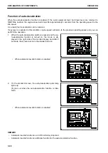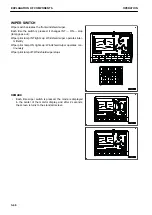
TRAVEL SPEED DISPLAY
The travel speed display shows the set mode of the travel
speed.
The travel speed is indicated as follows according to the setting
of the travel speed selector switch.
Lo: Low-speed travel
Hi: High-speed travel
ONE-TOUCH POWER MAXIMIZING PILOT LAMP
One-touch power maximizing pilot lamp shows if the one-touch
power maximizing function is being actuated.
The following pilot lamp is displayed when the knob switch on
the L.H. control lever is operated. (The actual pilot lamp display
is shown at the position of preheating pilot lamp.)
Pilot lamp lights up: Digging power increases while the knob
switch is kept pressed (for a maximum of 8.5 seconds).
Pilot lamp goes out: Power maximizing function is stopped
REMARK
Only when the working mode is P and E mode, the power is in-
creased while the knob switch is being pressed. Even if the
knob switch continues to be pressed, the power maximizing op-
eration ends in 8.5 seconds.
AIR CONDITIONER PILOT LAMP
The air conditioner pilot lamp shows the operating state of the
air conditioner.
Pilot lamp lights up: Air conditioner ON
Pilot lamp goes out: Air conditioner OFF
MESSAGE DISPLAY
The message display lights up when there is a message from
Komatsu.
To read the message, see “MESSAGE DISPLAY”.
Lights up in green (A): There is unread message.
Lights up in blue (B): There is any read message to which no
reply is made.
OFF: No messages
EXPLANATION OF COMPONENTS
OPERATION
3-32
Содержание PC700LC-11
Страница 2: ......
Страница 23: ...LOCATION OF SAFETY LABELS 5 SAFETY SAFETY LABELS 2 3...
Страница 66: ......
Страница 67: ...OPERATION Please read and make sure that you understand the SAFETY section before reading this section 3 1...
Страница 73: ...REMARK The above figure does not show all of the caution lamp symbols OPERATION GENERAL VIEW 3 7...
Страница 316: ......
Страница 317: ...MAINTENANCE Please read and make sure that you understand the SAFETY section before reading this section 4 1...
Страница 331: ...Fuel main fil ter cartridge Replace Replace Replace Replace MAINTENANCE MAINTENANCE SCHEDULE 4 15...
Страница 375: ...A Important inspection part F Front Revolving frame Center frame MAINTENANCE MAINTENANCE PROCEDURE 4 59...
Страница 396: ......
Страница 397: ...SPECIFICATIONS 5 1...
Страница 401: ...For 7 6m Boom SPECIFICATIONS SPECIFICATIONS 5 5...
Страница 402: ...SPECIFICATIONS SPECIFICATIONS 5 6...
Страница 426: ......
Страница 427: ...REPLACEMENT PARTS 7 1...
Страница 434: ......
Страница 442: ...PC700LC 11 HYDRAULIC EXCAVATOR Form No UENAM01321 2017 KOMATSU All Rights Reserved Printed in Belgium 09 2017...


