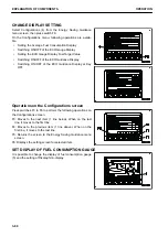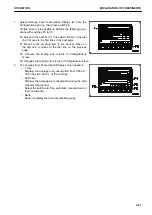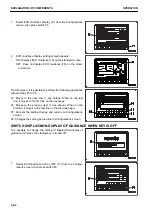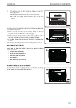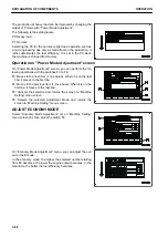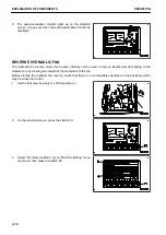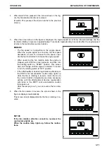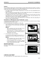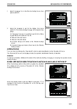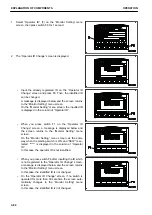
REMARK
• In some cases, the screen in step 3 does not change to
that in step 4 and the screen shown in the figure is dis-
played and the fan does not rotate in reverse. This hap-
pens when the fan rotation is controlled not to be reversed
for the hydraulic oil temperature condition to protect the
components.
• To reverse the fan rotation, press the switch F5 to return to
the standard screen. Then, run the engine at low idle to
warm-up.
• If background color of hydraulic oil temperature caution
lamp (1) is blue or red on the standard screen, the fan can
be rotated in reverse. Perform the procedure in order from
step 1.
• While the fan is rotating in reverse, the work equipment is
so controlled that it will move little even if it is operated.
The purpose of the fan reverse function is to clean the ra-
diator. When performing the actual work, including the
work equipment operation, set the fan rotation to the nor-
mal direction.
• If the fan rotation is reversed while KDPF system caution
lamp or KDPF soot accumulation caution lamp is lit, the
engine speed and fan speed may not increase even when
the fuel control dial is set to High idle (MAX) position, but
this is not a failure.
• In a cold circumstance, perform the cleaning by fan re-
verse rotation within less than 5 minutes. If reverse rota-
tion of the hydraulic fan is performed for a long time, DEF
hose may be frozen.
AUTO IDLE STOP TIMER SETTING
The auto idle stop function stops the engine automatically at the set time when the engine is operated continu-
ously at idle with the lock lever in LOCK position.
The auto idle stop function operates only when the following conditions are satisfied.
• The engine is running normally.
• The lock lever is in LOCK position.
• The engine coolant and hydraulic oil are not overheating.
• The engine is not in warm-up operation.
• The machine is not in the L mode.
You can set the time to operate the auto idle stop function on "Auto Idle Stop Timer Setting".
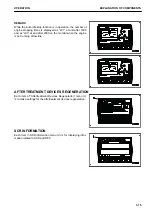
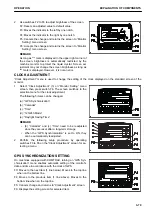
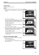
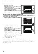
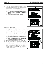
1.
Select “Auto Idle Stop Timer Setting” (5) on “Machine Set-
ting” menu (b) screen, then press the switch F6.
OPERATION
EXPLANATION OF COMPONENTS
3-73
Содержание PC700LC-11
Страница 2: ......
Страница 23: ...LOCATION OF SAFETY LABELS 5 SAFETY SAFETY LABELS 2 3...
Страница 66: ......
Страница 67: ...OPERATION Please read and make sure that you understand the SAFETY section before reading this section 3 1...
Страница 73: ...REMARK The above figure does not show all of the caution lamp symbols OPERATION GENERAL VIEW 3 7...
Страница 316: ......
Страница 317: ...MAINTENANCE Please read and make sure that you understand the SAFETY section before reading this section 4 1...
Страница 331: ...Fuel main fil ter cartridge Replace Replace Replace Replace MAINTENANCE MAINTENANCE SCHEDULE 4 15...
Страница 375: ...A Important inspection part F Front Revolving frame Center frame MAINTENANCE MAINTENANCE PROCEDURE 4 59...
Страница 396: ......
Страница 397: ...SPECIFICATIONS 5 1...
Страница 401: ...For 7 6m Boom SPECIFICATIONS SPECIFICATIONS 5 5...
Страница 402: ...SPECIFICATIONS SPECIFICATIONS 5 6...
Страница 426: ......
Страница 427: ...REPLACEMENT PARTS 7 1...
Страница 434: ......
Страница 442: ...PC700LC 11 HYDRAULIC EXCAVATOR Form No UENAM01321 2017 KOMATSU All Rights Reserved Printed in Belgium 09 2017...


