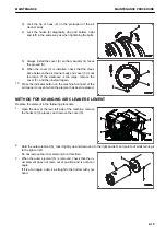
5.
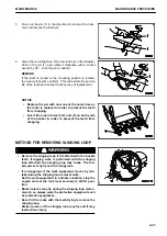
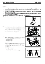
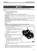
Push out the pin (1) in the direction of arrow with a ham-
mer, and remove the tooth (2).
6.
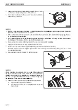
Clean the mounting face. Fit a new tooth (2) in the adapter.
Push in the pin (1), and rotate it clockwise with a socket
wrench by 90 °. Lock the pin to install it.
REMARK
If the tooth is turned or the mounting position is rotated,
the wear will become uniform. This will extend the service
life of the tooth and reduce the frequency of replacement.
NOTICE
• Replace the pin with new one at the same time as
the tooth is replaced in order to prevent the tooth
from dropping.
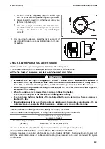
• Insert the pins into teeth (4) and (5) on both ends
of the bucket in order to prevent the teeth from
dropping.
METHOD FOR REMOVING SLINGING LOOP
k
k
WARNING
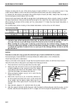
• Remove the slinging loop if it is attached to the bucket
teeth. If digging work is performed with the slinging
loop attached, the slinging loop may break. The bro-
ken pieces may fly and it is dangerous.
• It is dangerous if the work equipment moves by mis-
take during the slinging loop removal work.
Set the work equipment in a stable condition, stop the
engine and set the lock lever securely to LOCK posi-
tion.
• Broken pieces may fly during the slinging loop remov-
al work, so always wear the protective equipment such
as protective eyeglasses.
• Never hit the rocks with the teeth trying to remove the
slinging loop.
Broken pieces of the slinging loop may fly and it may
lead serious injury.
MAINTENANCE
MAINTENANCE PROCEDURE
4-27
Содержание PC700LC-11
Страница 2: ......
Страница 23: ...LOCATION OF SAFETY LABELS 5 SAFETY SAFETY LABELS 2 3...
Страница 66: ......
Страница 67: ...OPERATION Please read and make sure that you understand the SAFETY section before reading this section 3 1...
Страница 73: ...REMARK The above figure does not show all of the caution lamp symbols OPERATION GENERAL VIEW 3 7...
Страница 316: ......
Страница 317: ...MAINTENANCE Please read and make sure that you understand the SAFETY section before reading this section 4 1...
Страница 331: ...Fuel main fil ter cartridge Replace Replace Replace Replace MAINTENANCE MAINTENANCE SCHEDULE 4 15...
Страница 375: ...A Important inspection part F Front Revolving frame Center frame MAINTENANCE MAINTENANCE PROCEDURE 4 59...
Страница 396: ......
Страница 397: ...SPECIFICATIONS 5 1...
Страница 401: ...For 7 6m Boom SPECIFICATIONS SPECIFICATIONS 5 5...
Страница 402: ...SPECIFICATIONS SPECIFICATIONS 5 6...
Страница 426: ......
Страница 427: ...REPLACEMENT PARTS 7 1...
Страница 434: ......
Страница 442: ...PC700LC 11 HYDRAULIC EXCAVATOR Form No UENAM01321 2017 KOMATSU All Rights Reserved Printed in Belgium 09 2017...

