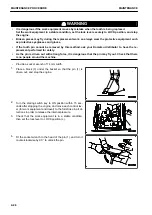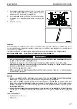
3.
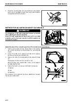
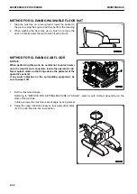
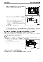
Lower the work equipment to the ground and set the ma-
chine in a stable condition.
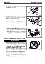
4.
Operate the control grip (g) of the lock lever (1) to set it se-
curely to LOCK position (L) and stop the engine.
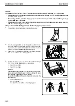
5.
Pull out projections (2) (6 places) on the back of the floor
mat and remove the floor mat.
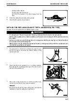
6.
Remove the cap from water drain hole (3).
7.
Flush out the dirt on the floor directly with water through
water drain hole (3).
8.
After completing the washing work, install the cap in water
drain hole (3).
9.
Fit the floor mat and secure it by inserting projections (2)
into the holes.
MAINTENANCE
MAINTENANCE PROCEDURE
4-35
Содержание PC700LC-11
Страница 2: ......
Страница 23: ...LOCATION OF SAFETY LABELS 5 SAFETY SAFETY LABELS 2 3...
Страница 66: ......
Страница 67: ...OPERATION Please read and make sure that you understand the SAFETY section before reading this section 3 1...
Страница 73: ...REMARK The above figure does not show all of the caution lamp symbols OPERATION GENERAL VIEW 3 7...
Страница 316: ......
Страница 317: ...MAINTENANCE Please read and make sure that you understand the SAFETY section before reading this section 4 1...
Страница 331: ...Fuel main fil ter cartridge Replace Replace Replace Replace MAINTENANCE MAINTENANCE SCHEDULE 4 15...
Страница 375: ...A Important inspection part F Front Revolving frame Center frame MAINTENANCE MAINTENANCE PROCEDURE 4 59...
Страница 396: ......
Страница 397: ...SPECIFICATIONS 5 1...
Страница 401: ...For 7 6m Boom SPECIFICATIONS SPECIFICATIONS 5 5...
Страница 402: ...SPECIFICATIONS SPECIFICATIONS 5 6...
Страница 426: ......
Страница 427: ...REPLACEMENT PARTS 7 1...
Страница 434: ......
Страница 442: ...PC700LC 11 HYDRAULIC EXCAVATOR Form No UENAM01321 2017 KOMATSU All Rights Reserved Printed in Belgium 09 2017...

