2.
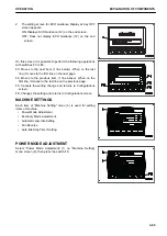
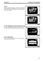
Use switches F2 to F6 to adjust brightness of the screen.
F2: Resets an adjusted value to default value.
F3: Moves the indicator to the left by one notch.
F4: Moves the indicator to the right by one notch.
F5: Cancels the change and returns the screen to “Monitor
Setting” menu screen.
F6: Accepts the change and returns the screen to “Monitor
Setting” menu screen.
REMARK
As long as "*" mark is displayed in the upper right corner of
the screen, brightness is automatically restricted by the
machine monitor to protect the liquid crystal. Screen ad-
justment may not change the screen brightness as long as
"*" mark is displayed. However, it is not an error.
CLOCK ADJUSTMENT
“Clock Adjustment” menu is used to change the setting of the clock displayed on the standard screen of the
monitor.
1.
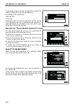
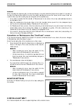
Select “Clock Adjustment” (3) on “Monitor Setting” menu
screen, then press switch F6. The screen switches to the
selection menu for the clock adjustment.
The following 5 items can be changed.
(a): “GPS Synchronization”
(b): “Calendar”
(c): “Time”
(d): “12h/24h Mode”
(e): “Daylight Saving Time”
REMARK
• (b) “Calendar” and (c) “Time” need to be readjusted
since they are reset after a long-term storage.
• When the “GPS Synchronization” is set to ON, they
can be automatically readjusted.
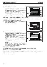
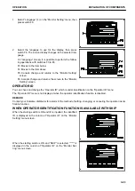
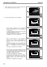
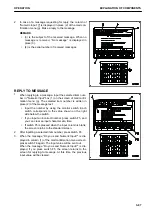
2.
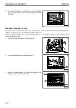
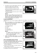
Perform the following setup procedure by operating
switches F3 to F6 on the “Clock Adjustment” screen for se-
lecting a menu.
GPS SYNCHRONIZATION SETTING
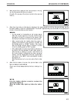
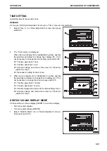
On machines equipped with KOMTRAX, turning on “GPS Syn-
chronization” menu enables automatic setting of the monitor's
date and time in accordance with the clock of GPS.
F3: Moves to the next item (1 line below). Moves to the top line
when on the bottom line.
F4: Moves to the previous item (1 line above). Moves to the
bottom line when on the top line.
F5: Cancels change and returns to “Clock Adjustment” screen.
F6: Displays the setting screen for selected item.
OPERATION
EXPLANATION OF COMPONENTS
3-79
Содержание PC700LC-11
Страница 2: ......
Страница 23: ...LOCATION OF SAFETY LABELS 5 SAFETY SAFETY LABELS 2 3...
Страница 66: ......
Страница 67: ...OPERATION Please read and make sure that you understand the SAFETY section before reading this section 3 1...
Страница 73: ...REMARK The above figure does not show all of the caution lamp symbols OPERATION GENERAL VIEW 3 7...
Страница 316: ......
Страница 317: ...MAINTENANCE Please read and make sure that you understand the SAFETY section before reading this section 4 1...
Страница 331: ...Fuel main fil ter cartridge Replace Replace Replace Replace MAINTENANCE MAINTENANCE SCHEDULE 4 15...
Страница 375: ...A Important inspection part F Front Revolving frame Center frame MAINTENANCE MAINTENANCE PROCEDURE 4 59...
Страница 396: ......
Страница 397: ...SPECIFICATIONS 5 1...
Страница 401: ...For 7 6m Boom SPECIFICATIONS SPECIFICATIONS 5 5...
Страница 402: ...SPECIFICATIONS SPECIFICATIONS 5 6...
Страница 426: ......
Страница 427: ...REPLACEMENT PARTS 7 1...
Страница 434: ......
Страница 442: ...PC700LC 11 HYDRAULIC EXCAVATOR Form No UENAM01321 2017 KOMATSU All Rights Reserved Printed in Belgium 09 2017...

