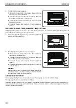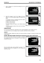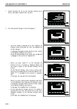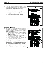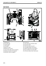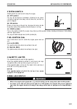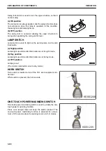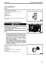
CONTROL LEVERS AND PEDALS
(1) Lock lever
(2) Travel levers (with pedal and auto-deceleration
system)
(3) L.H. work equipment control lever (with auto-decel-
eration system)
(4) R.H. work equipment control lever (with auto-de-
celeration system)
LOCK LEVER
k
k
WARNING
• When leaving the operator's seat, set the lock lever securely to LOCK position. If the lock lever is
not at LOCK position and the control levers or control pedals are touched by mistake, it may lead to
serious personal injury or death.
• Always check that the lock lever is in LOCK position.
• When pulling the lock lever up, or when pushing the lock lever down, be careful not to touch the
work equipment control lever.
• Before setting the lock lever to FREE position, make sure that all control levers and pedals are set
to NEUTRAL position. If any of them is out of NEUTRAL position, the work equipment or machine
may move suddenly and cause a serious personal injury or death.
The lock lever is a device to lock the work equipment, swing,
travel, and attachment control levers (if equipped).
(L) LOCK position
Even when levers or attachment control pedal (if equipped) are
operated, machine does not move
(F) FREE position
Machine moves according to operation of levers or attachment
control pedal (if equipped).
EXPLANATION OF COMPONENTS
OPERATION
3-96
Содержание PC700LC-11
Страница 2: ......
Страница 23: ...LOCATION OF SAFETY LABELS 5 SAFETY SAFETY LABELS 2 3...
Страница 66: ......
Страница 67: ...OPERATION Please read and make sure that you understand the SAFETY section before reading this section 3 1...
Страница 73: ...REMARK The above figure does not show all of the caution lamp symbols OPERATION GENERAL VIEW 3 7...
Страница 316: ......
Страница 317: ...MAINTENANCE Please read and make sure that you understand the SAFETY section before reading this section 4 1...
Страница 331: ...Fuel main fil ter cartridge Replace Replace Replace Replace MAINTENANCE MAINTENANCE SCHEDULE 4 15...
Страница 375: ...A Important inspection part F Front Revolving frame Center frame MAINTENANCE MAINTENANCE PROCEDURE 4 59...
Страница 396: ......
Страница 397: ...SPECIFICATIONS 5 1...
Страница 401: ...For 7 6m Boom SPECIFICATIONS SPECIFICATIONS 5 5...
Страница 402: ...SPECIFICATIONS SPECIFICATIONS 5 6...
Страница 426: ......
Страница 427: ...REPLACEMENT PARTS 7 1...
Страница 434: ......
Страница 442: ...PC700LC 11 HYDRAULIC EXCAVATOR Form No UENAM01321 2017 KOMATSU All Rights Reserved Printed in Belgium 09 2017...

