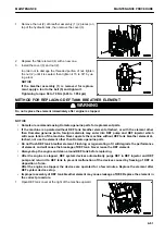
7.
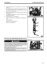
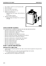
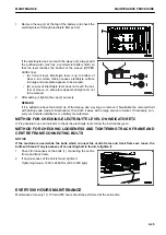
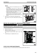
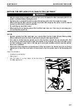
After replacing the filter cartridge, open the engine hood
and fill with engine oil through oil filler port (F) to the mid-
point between H and L marks on dipstick (G).
8.
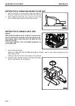
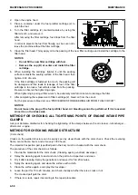
Run the engine at idle for a time, then stop the engine.
Check that the oil level is between H and L marks on the
dipstick.
9.
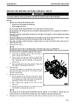
Install the cover (1).
REMARK
When the ambient temperature is low, water or emulsified matter may stick to the dipstick, oil filler cap, etc. or
the drained oil may be milky white because of water vapor in the blowby gas. However, if the coolant level is
normal, it is not a problem.
There is no problem even if the emulsified matter cannot be removed completely after changing the oil.
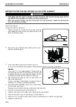
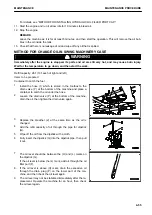
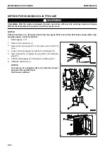
METHOD FOR REPLACING FUEL PREFILTER CARTRIDGE
k
k
WARNING
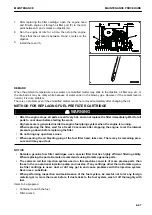
• After the engine stops, all parts are still very hot, so do not replace the filter immediately. Wait for all
parts to cool down before starting the work.
• High pressure is generated inside the engine fuel piping system when the engine is running.
When replacing the filter, wait for at least 30 seconds after stopping the engine to let the internal
pressure go down before replacing the filter.
• Do not bring any open flame close.
• When opening the air bleeding plug of the fuel filter head, take care. There may be remaining pres-
sure and it may spurt out.
NOTICE
• Komatsu genuine fuel filter cartridges use a special filter that has highly efficient filtering ability.
When replacing the parts, Komatsu recommends using Komatsu genuine parts.
• The common rail fuel injection system used on this machine consists of more precise parts than
those in the conventional injection pump and nozzles. If any cartridge other than a Komatsu genu-
ine filter cartridge is used, dust or dirt may get in and cause problems with the injection system.
Never use a substitute.
• When performing inspection and maintenance of the fuel system, be careful not to let any foreign
material get in, more than ever before. If dust sticks to the fuel system, wash it off thoroughly with
fuel.
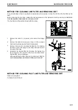
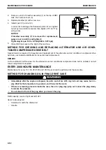
Items to be prepared
• Container to catch the fuel
• Filter wrench
MAINTENANCE
MAINTENANCE PROCEDURE
4-47
Содержание PC700LC-11
Страница 2: ......
Страница 23: ...LOCATION OF SAFETY LABELS 5 SAFETY SAFETY LABELS 2 3...
Страница 66: ......
Страница 67: ...OPERATION Please read and make sure that you understand the SAFETY section before reading this section 3 1...
Страница 73: ...REMARK The above figure does not show all of the caution lamp symbols OPERATION GENERAL VIEW 3 7...
Страница 316: ......
Страница 317: ...MAINTENANCE Please read and make sure that you understand the SAFETY section before reading this section 4 1...
Страница 331: ...Fuel main fil ter cartridge Replace Replace Replace Replace MAINTENANCE MAINTENANCE SCHEDULE 4 15...
Страница 375: ...A Important inspection part F Front Revolving frame Center frame MAINTENANCE MAINTENANCE PROCEDURE 4 59...
Страница 396: ......
Страница 397: ...SPECIFICATIONS 5 1...
Страница 401: ...For 7 6m Boom SPECIFICATIONS SPECIFICATIONS 5 5...
Страница 402: ...SPECIFICATIONS SPECIFICATIONS 5 6...
Страница 426: ......
Страница 427: ...REPLACEMENT PARTS 7 1...
Страница 434: ......
Страница 442: ...PC700LC 11 HYDRAULIC EXCAVATOR Form No UENAM01321 2017 KOMATSU All Rights Reserved Printed in Belgium 09 2017...

