NOTICE
If the engine oil pressure caution lamp does not go out
in 4 to 5 seconds, stop the engine immediately. Check
the oil level, oil leakage, etc. and take proper meas-
ures.
REMARK
White smoke may be discharged for a short time immedi-
ately after the engine is started or during the aftertreatment
devices regeneration in the cold season, but this is not a
failure.
REMARK
Urea SCR system has the function of heating and keeping itself warm to prevent freezing of DEF.
If DEF is frozen, DEF system is heated and thawed automatically after the engine starts. The devices do
not operate until DEF is thawed and supplied, but this does not indicate any abnormality.
When the ambient temperature decreases so much that DEF may freeze while the machine is in operation,
DEF system is warmed automatically to prevent freezing. When the ambient temperature decreases so
much that freezing of DEF is not preventable, the devices stop automatically, but this does not indicate any
abnormality.
If DEF freezes, thawing operation is performed automatically. Never heat DEF. Harmful ammonia gas may
be generated.
METHOD FOR MANUAL PREHEATING WHEN STARTING ENGINE
Regardless of the ambient temperature, it is possible to start the engine preheating manually.
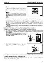
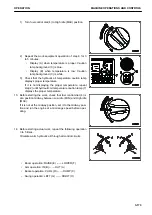
1.
Turn the key in starting switch (3) counterclockwise from OFF position (A). The preheating pilot lamp lights
up and preheating of the engine starts. (Preheating continues while the key in starting switch (3) is held
counterclockwise.)
The preheating pilot lamp starts flashing approximately 30
seconds after preheating starts and then goes out in ap-
proximately 10 seconds.
2.
After the preheating pilot lamp goes out, turn the key of
starting switch (3) to START position (C). The engine
starts.
If the engine cannot be started with the above procedure, wait for approximately 2 minutes, then start again
from step 1.
TURBOCHARGER PROTECTION FUNCTION
The turbo protect function protects the turbocharger by keeping the engine speed at approximately 1000 rpm or
less immediately after the engine is started.
OPERATION
MACHINE OPERATIONS AND CONTROLS
3-165
Содержание PC700LC-11
Страница 2: ......
Страница 23: ...LOCATION OF SAFETY LABELS 5 SAFETY SAFETY LABELS 2 3...
Страница 66: ......
Страница 67: ...OPERATION Please read and make sure that you understand the SAFETY section before reading this section 3 1...
Страница 73: ...REMARK The above figure does not show all of the caution lamp symbols OPERATION GENERAL VIEW 3 7...
Страница 316: ......
Страница 317: ...MAINTENANCE Please read and make sure that you understand the SAFETY section before reading this section 4 1...
Страница 331: ...Fuel main fil ter cartridge Replace Replace Replace Replace MAINTENANCE MAINTENANCE SCHEDULE 4 15...
Страница 375: ...A Important inspection part F Front Revolving frame Center frame MAINTENANCE MAINTENANCE PROCEDURE 4 59...
Страница 396: ......
Страница 397: ...SPECIFICATIONS 5 1...
Страница 401: ...For 7 6m Boom SPECIFICATIONS SPECIFICATIONS 5 5...
Страница 402: ...SPECIFICATIONS SPECIFICATIONS 5 6...
Страница 426: ......
Страница 427: ...REPLACEMENT PARTS 7 1...
Страница 434: ......
Страница 442: ...PC700LC 11 HYDRAULIC EXCAVATOR Form No UENAM01321 2017 KOMATSU All Rights Reserved Printed in Belgium 09 2017...


