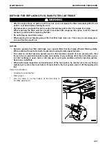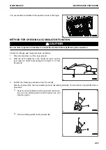
2.
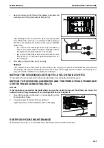
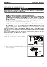
Open the engine hood.
3.
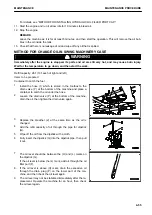
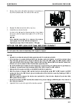
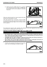
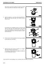
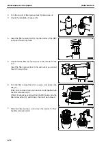
Place a container under the fuel prefilter cartridge (2) to
catch the fuel.
4.
Turn the filter cartridge (2) counterclockwise by using the
filter wrench, and remove it.
After removing the filter cartridge, fuel drops from the filter
head.
In order to prevent the fuel from flowing out, be sure not to
leave the machine without the filter cartridge.
5.
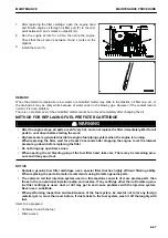
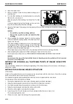
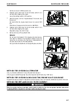
Clean the filter head. Thinly apply oil to the packing of the new filter cartridge and install the cartridge to the
filter head.
NOTICE
• Do not fill the new filter cartridge with fuel.
• Remove the cap (B) at center and install the filter
cartridge.
6.
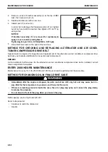
When installing the cartridge, tighten it until the packing
surface contacts the sealing surface of the filter head, then
tighten it 3/4 of a turn.
If the filter cartridge is fastened too much, the packing will
be damaged and this leads to leakage of fuel. If the filter
cartridge is too loose, fuel will also leak from the packing.
Be sure to observe the tightening angle.
When tightening by using a filter wrench, be extremely careful not to dent or damage the filter.
7.
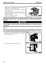
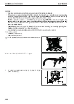
After completing the replacement of filter cartridge (2), bleed air from the circuit.
For the procedure to bleed air, see “PROCEDURES FOR BLEEDING AIR FROM FUEL CIRCUIT”.
NOTICE
Do not loosen the plug of the fuel prefilter head. Air bleeding cannot be performed if it is loosened
since it is on the intake side.
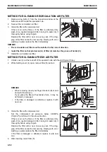
METHOD FOR CHECKING ALL TIGHTENING POINTS OF ENGINE INTAKE PIPE
CLAMPS
Ask your Komatsu distributor for checking the tightening of the clamps between the air cleaner - turbocharger -
aftercooler - engine.
METHOD FOR CHECKING WELDED STRUCTURE
(Color check)
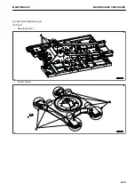
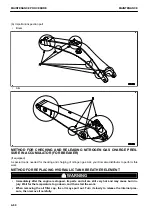
Cracks on the welded structure can be easily seen by visual check with the color check. Check the revolving
frame, center frame, boom, and arm every 1000 hours.
The important inspection part (specified part in the box) must be checked with the color check.
The procedure of the color check is as follows.
1.
Provide the materials for the color check. (Cleaning agent, penetrant, developer)
2.
Spray the cleaning agent to dust and oil on the part to be inspected, and clean.
3.
Dry it after cleaning. Spray the penetrant, and leave it for 5 to 20 minutes.
4.
Spray the cleaning agent, and clean the surface with a cloth.
5.
Clean the surface again, and spray the developer.
6.
Leave the part for 15 to 20 minutes, and check visually whether there is a crack or not.
The cracked part gets the color.
7.
If there is a crack, repair it according to the repair procedure.
MAINTENANCE PROCEDURE
MAINTENANCE
4-58
Содержание PC700LC-11
Страница 2: ......
Страница 23: ...LOCATION OF SAFETY LABELS 5 SAFETY SAFETY LABELS 2 3...
Страница 66: ......
Страница 67: ...OPERATION Please read and make sure that you understand the SAFETY section before reading this section 3 1...
Страница 73: ...REMARK The above figure does not show all of the caution lamp symbols OPERATION GENERAL VIEW 3 7...
Страница 316: ......
Страница 317: ...MAINTENANCE Please read and make sure that you understand the SAFETY section before reading this section 4 1...
Страница 331: ...Fuel main fil ter cartridge Replace Replace Replace Replace MAINTENANCE MAINTENANCE SCHEDULE 4 15...
Страница 375: ...A Important inspection part F Front Revolving frame Center frame MAINTENANCE MAINTENANCE PROCEDURE 4 59...
Страница 396: ......
Страница 397: ...SPECIFICATIONS 5 1...
Страница 401: ...For 7 6m Boom SPECIFICATIONS SPECIFICATIONS 5 5...
Страница 402: ...SPECIFICATIONS SPECIFICATIONS 5 6...
Страница 426: ......
Страница 427: ...REPLACEMENT PARTS 7 1...
Страница 434: ......
Страница 442: ...PC700LC 11 HYDRAULIC EXCAVATOR Form No UENAM01321 2017 KOMATSU All Rights Reserved Printed in Belgium 09 2017...


