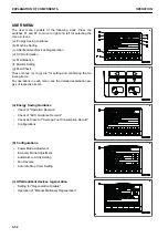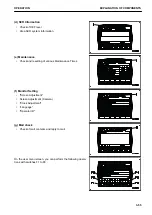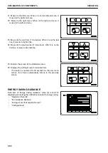
(J) Switch F5: Cancels any change and returns the screen to
the previous screen.
(K) Switch F6: Enters the selection and contents to change,
and proceeds the screen to the next screen.
REMARK
• Even if some icons look the same, their display positions
and corresponding function switches may differ according
to the screens to be displayed.
• For the guidance icons and their functions not explained
above, see the pages where the control methods of re-
spective screens are explained.
WORKING MODE SELECTOR SWITCH
Use the working mode selector switch (1) to set the movement
or power of the work equipment.
The operation becomes easier by selecting the mode to match
the content of the operation.
P mode: For heavy-duty operations
E mode: For operations with emphasis on fuel consumption
L mode: For fine control operations
• When the monitor is turned on, it is automatically set to the
mode used when the starting switch was turned to OFF
position last.
• Press the switch to display the working mode selection
screen. For each set mode, P, E, and L are displayed on
the working mode display (2) at the top right of the ma-
chine monitor display.
Ask your Komatsu distributor to change the setting if you want
to have an automatic setting of P, E, and L mode (optional de-
fault setting) when starting the engine.
How to use the working mode selector switch
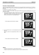
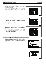
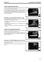
1.
When working mode selector switch (1) is pressed, the
working mode selector screen is displayed on the monitor.
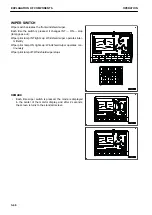
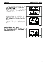
2.
Press the switches F3 or F4 at the bottom of the screen or working mode selector switch (1) to change the
mode selection one at a time.
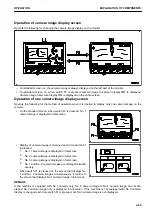
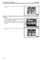
If no switch is touched for more than 5 seconds, the selected working mode is automatically set as the
working mode. The screen changes to the one for the steps 3 and 4.
EXPLANATION OF COMPONENTS
OPERATION
3-42
Содержание PC700LC-11
Страница 2: ......
Страница 23: ...LOCATION OF SAFETY LABELS 5 SAFETY SAFETY LABELS 2 3...
Страница 66: ......
Страница 67: ...OPERATION Please read and make sure that you understand the SAFETY section before reading this section 3 1...
Страница 73: ...REMARK The above figure does not show all of the caution lamp symbols OPERATION GENERAL VIEW 3 7...
Страница 316: ......
Страница 317: ...MAINTENANCE Please read and make sure that you understand the SAFETY section before reading this section 4 1...
Страница 331: ...Fuel main fil ter cartridge Replace Replace Replace Replace MAINTENANCE MAINTENANCE SCHEDULE 4 15...
Страница 375: ...A Important inspection part F Front Revolving frame Center frame MAINTENANCE MAINTENANCE PROCEDURE 4 59...
Страница 396: ......
Страница 397: ...SPECIFICATIONS 5 1...
Страница 401: ...For 7 6m Boom SPECIFICATIONS SPECIFICATIONS 5 5...
Страница 402: ...SPECIFICATIONS SPECIFICATIONS 5 6...
Страница 426: ......
Страница 427: ...REPLACEMENT PARTS 7 1...
Страница 434: ......
Страница 442: ...PC700LC 11 HYDRAULIC EXCAVATOR Form No UENAM01321 2017 KOMATSU All Rights Reserved Printed in Belgium 09 2017...


