1.
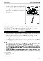
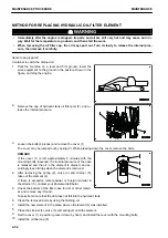
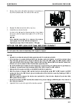
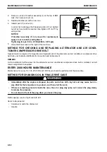
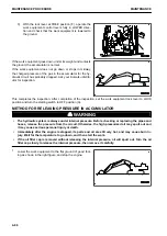
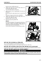
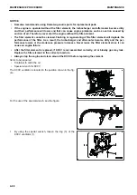
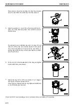
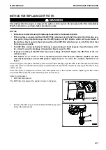
Remove the nut (2) of breather assembly (1) (2 pieces) on
top of the hydraulic tank, then remove the cover (3).
2.
Replace the filter element (4) with a new one.
3.
Install the cover (3) and nut (2).
In order not to damage the threaded portion of nut, tighten
the nut (2) until it is seated, then tighten it 15 to 30° by us-
ing a tool.
NOTICE
If the breather assembly (1) is removed for replace-
ment, apply a tool to the bolt (5) and tighten it.
Tightening torque: 68 to 78 Nm {6.93 to 7.95 kgm}
METHOD FOR REPLACING DEF TANK BREATHER ELEMENT
k
k
WARNING
Do not replace the element immediately after engine is stopped.
NOTICE
• Komatsu recommends using Komatsu genuine parts for replacement parts.
• If the machine is operated without DEF tank breather element attached, or with the element other
than Komatsu genuine parts, foreign materials may enter into DEF pump and DEF injector which
will cause failure of the machine. Never operate the machine without DEF tank breather element at-
tached, nor use the element other than Komatsu genuine parts.
• Do not flush DEF tank breather element. Flushing or regenerating of it will degrade the performance
of element, and will cause the breakage of DEF tank. Never reuse the DEF element.
• Always stop the engine and clean around DEF tank before replacing.
• After the engine is stopped, DEF system devices automatically purge DEF in DEF injector and DEF
pump and return it to DEF tank to prevent malfunction of the devices caused by freezing of DEF or
deposition of urea.
After the engine is stopped, the devices are operated for a few minutes. Replace the element after
DEF system devices stop.
• Improper assembly of DEF tank breather element may cause leakage of DEF. Replace the element in
the correct procedure.
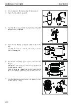
1.
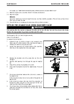
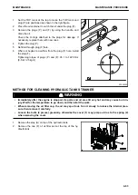
Open DEF tank cover at the right of the machine upward.
MAINTENANCE
MAINTENANCE PROCEDURE
4-61
Содержание PC700LC-11
Страница 2: ......
Страница 23: ...LOCATION OF SAFETY LABELS 5 SAFETY SAFETY LABELS 2 3...
Страница 66: ......
Страница 67: ...OPERATION Please read and make sure that you understand the SAFETY section before reading this section 3 1...
Страница 73: ...REMARK The above figure does not show all of the caution lamp symbols OPERATION GENERAL VIEW 3 7...
Страница 316: ......
Страница 317: ...MAINTENANCE Please read and make sure that you understand the SAFETY section before reading this section 4 1...
Страница 331: ...Fuel main fil ter cartridge Replace Replace Replace Replace MAINTENANCE MAINTENANCE SCHEDULE 4 15...
Страница 375: ...A Important inspection part F Front Revolving frame Center frame MAINTENANCE MAINTENANCE PROCEDURE 4 59...
Страница 396: ......
Страница 397: ...SPECIFICATIONS 5 1...
Страница 401: ...For 7 6m Boom SPECIFICATIONS SPECIFICATIONS 5 5...
Страница 402: ...SPECIFICATIONS SPECIFICATIONS 5 6...
Страница 426: ......
Страница 427: ...REPLACEMENT PARTS 7 1...
Страница 434: ......
Страница 442: ...PC700LC 11 HYDRAULIC EXCAVATOR Form No UENAM01321 2017 KOMATSU All Rights Reserved Printed in Belgium 09 2017...

