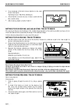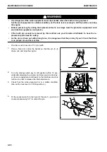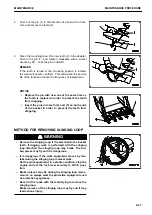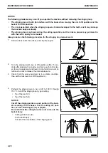
• When the oil inside the swing motor case is drained
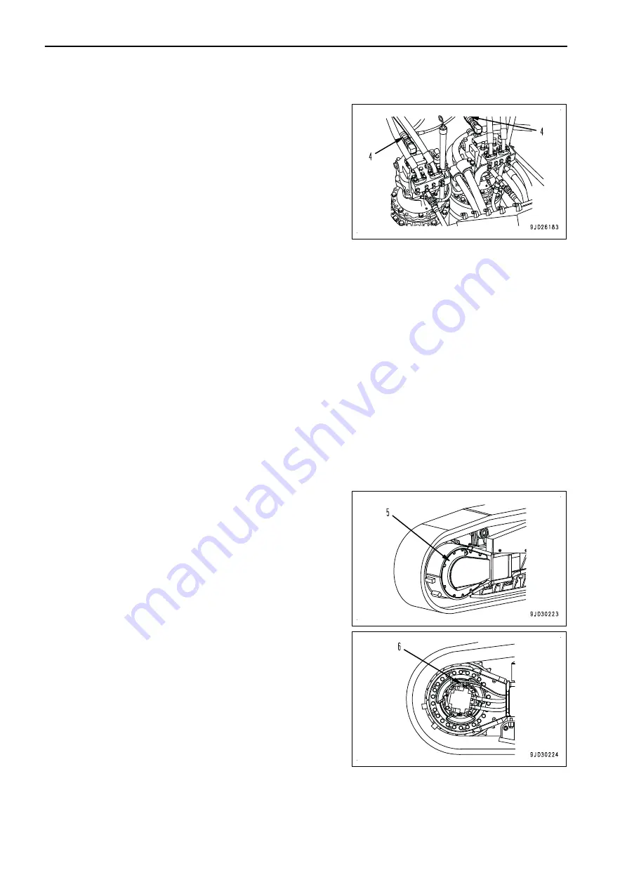
1) Run the engine at low idle, loosen the hose (4) at port
S, and check that oil oozes out from the port S hose
(4).
NOTICE
At this time, do not perform the swing operation.
2) If oil does not ooze out, stop the engine, remove the
port S hose (4), and fill the motor case with hydraulic
oil.
3) After completely bleeding the air from the swing motor,
tighten the port S hose (4).
4) Run the engine at low idle and slowly swing at least 2 turns uniformly to the right and left.
NOTICE
• If the air is not bled from the swing motor, the motor bearings may be damaged.
• Perform the air bleeding according to the above procedure when the swing motor safety
valve is replaced.
5.
Bleeding air from attachment (when installed)
If an attachment is installed, operate the attachment pedal repeatedly (approximately 10 times) with the en-
gine running at low idle until the air is completely bled from the attachment circuit.
NOTICE
• If the attachment has its own air bleeding procedure specified by the manufacturer, observe
them.
• After completing the air bleeding operation, stop the engine, leave the machine as it is for 5 mi-
nutes or longer, and then start the operation again. This will remove the air bubbles in the oil
inside the tank.
• Check for oil leakage and wipe off any spilled oil.
6.
Bleeding air from travel motor circuit
If the piping of the travel motor is removed once and as-
sembled again afterwards, run the engine at low idle, and
perform the following to bleed air from the circuit.
1) Start the engine, and run it at low idle.
2) Remove the travel motor cover (5), and loosen the air
bleeding plug (6) 1 turn.
NOTICE
Never loosen the plug (6) more than 1 turn.
3) When oil which is not milky white comes out through
the air bleeding plug (6), tighten the air bleeding plug
(6).
4) Operate the fine control of the travel lever forward and
reverse for 4 to 5 times.
5) Install the travel motor cover (5).
7.
Operating
1) After completing the air bleeding, stop the engine,
leave the machine as it is for 5 minutes, and then start
the operation. This will remove the air bubbles in the
oil inside the tank.
2) Check that there is no leakage of oil and wipe off any oil that is spilled.
MAINTENANCE PROCEDURE
MAINTENANCE
4-38
Содержание PC700LC-11
Страница 2: ......
Страница 23: ...LOCATION OF SAFETY LABELS 5 SAFETY SAFETY LABELS 2 3...
Страница 66: ......
Страница 67: ...OPERATION Please read and make sure that you understand the SAFETY section before reading this section 3 1...
Страница 73: ...REMARK The above figure does not show all of the caution lamp symbols OPERATION GENERAL VIEW 3 7...
Страница 316: ......
Страница 317: ...MAINTENANCE Please read and make sure that you understand the SAFETY section before reading this section 4 1...
Страница 331: ...Fuel main fil ter cartridge Replace Replace Replace Replace MAINTENANCE MAINTENANCE SCHEDULE 4 15...
Страница 375: ...A Important inspection part F Front Revolving frame Center frame MAINTENANCE MAINTENANCE PROCEDURE 4 59...
Страница 396: ......
Страница 397: ...SPECIFICATIONS 5 1...
Страница 401: ...For 7 6m Boom SPECIFICATIONS SPECIFICATIONS 5 5...
Страница 402: ...SPECIFICATIONS SPECIFICATIONS 5 6...
Страница 426: ......
Страница 427: ...REPLACEMENT PARTS 7 1...
Страница 434: ......
Страница 442: ...PC700LC 11 HYDRAULIC EXCAVATOR Form No UENAM01321 2017 KOMATSU All Rights Reserved Printed in Belgium 09 2017...

