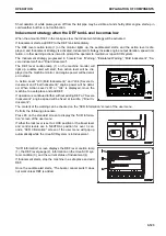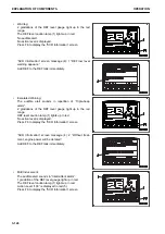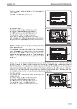
“SCR Information” screen message (4): 5 “Engine is run-
ning at low idle.”
Engine speed is fixed at low idle to disable practical ma-
chine operation.
Add DEF to the DEF tank immediately.
In case the system does not come out of Inducement even
if DEF is added in the tank, contact your Komatsu Distribu-
tor.
Inducement strategy when abnormalities are detected in the Urea SCR system
devices (Except abnormalities in the KDPF system)
If any abnormality is detected in the DEF quality or in the Urea SCR system, the Inducement strategy is activa-
ted.
The inducement strategy progresses in 5 levels, “Warning”,
“Escalated Warning”, “Mild Inducement”, “Severe Inducement”
and “Final Inducement”. The Inducement strategy includes vis-
ual alert by the DEF caution lamp, the KDPF system caution
lamp or the Engine system caution lamp (1), and Action Level
displayed on the machine monitor (2), and the audible alert by
a buzzer and stepwise engine power deration that advances to
speed limitation to low idle. Engine power deration starts with
Action Level “L03 (Mild Inducement)” and advances to further
deration when “L04 (Severe Inducement and Final Induce-
ment)” is displayed. Once the system advances to “Final In-
ducement”, the engine speed is fixed to low idle. If “L03” is dis-
played, move the machine to a safe place and contact your Komatsu distributor.
The content of the warning can be checked on the “SCR Information” screen of the user menu.
Perform the following procedure.
Press F6 on the standard screen to display the “SCR Informa-
tion” screen of the user menu.
If either the lock lever is set to LOCK position or the travel lever
and control levers are in NEUTRAL position for over 3 sec-
onds, “SCR Information” screen of the user menu will pop up
automatically while the Urea SCR system is in Inducement.
“SCR Information” screen displays remaining time (Hours and
Minutes) to the next Inducement status in the column (5), and
information on the Urea SCR system condition (3), and the cur-
rent status of Inducement (4).
EXPLANATION OF COMPONENTS
OPERATION
3-126
Содержание PC700LC-11
Страница 2: ......
Страница 23: ...LOCATION OF SAFETY LABELS 5 SAFETY SAFETY LABELS 2 3...
Страница 66: ......
Страница 67: ...OPERATION Please read and make sure that you understand the SAFETY section before reading this section 3 1...
Страница 73: ...REMARK The above figure does not show all of the caution lamp symbols OPERATION GENERAL VIEW 3 7...
Страница 316: ......
Страница 317: ...MAINTENANCE Please read and make sure that you understand the SAFETY section before reading this section 4 1...
Страница 331: ...Fuel main fil ter cartridge Replace Replace Replace Replace MAINTENANCE MAINTENANCE SCHEDULE 4 15...
Страница 375: ...A Important inspection part F Front Revolving frame Center frame MAINTENANCE MAINTENANCE PROCEDURE 4 59...
Страница 396: ......
Страница 397: ...SPECIFICATIONS 5 1...
Страница 401: ...For 7 6m Boom SPECIFICATIONS SPECIFICATIONS 5 5...
Страница 402: ...SPECIFICATIONS SPECIFICATIONS 5 6...
Страница 426: ......
Страница 427: ...REPLACEMENT PARTS 7 1...
Страница 434: ......
Страница 442: ...PC700LC 11 HYDRAULIC EXCAVATOR Form No UENAM01321 2017 KOMATSU All Rights Reserved Printed in Belgium 09 2017...


