1.
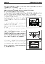
Press F5 while the “Engine Power Recovery” window is
displayed.
This procedure is split from procedure 4 in “Temporary Re-
storation from Inducement”.
“SCR Information” screen is displayed.
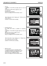
2.
Move any operating lever to display “Standard Screen” is
displayed.
“Temporary Restoration from Inducement” is deactivated.
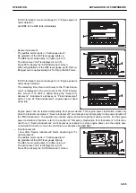
Inducement Strategy for abnormalities recurrences within 40 hours
The Urea SCR system continuously monitors its operation conditions and stores information on inappropriate
operations including malfunctions. The stored information is utilized to monitor recurrences of abnormalities,
“Abnormality Recurrence Counter”. “Abnormality Recurrence Counter” is required by the U.S. Environmental
Protection Agency. The recurrence monitoring spans 40 hours and it monitors the abnormalities that trigger In-
ducement other than the amount of DEF in the tank.
If another abnormality/abnormalities is detected within 40 hours after the previous abnormalities were corrected,
regardless of the level of the previous Inducement and whether the new abnormality/abnormalities is the same
as the previous ones or not, it is judged as a recurrence.
If a recurrence occurs, “Severe Inducement” will be activated. If this occurs, utilize “Temporary Restoration from
Inducement” and move the machine to a safe place, and contact your Komatsu distributor.
The duration of “Severe Inducement” in the recurrence is limited to 30 minutes. If the abnormalities are not cor-
rected while Inducement is in “Severe Inducement (30 minutes)”, Inducement will advance to “Final Inducement”
and engine speed will be fixed to low idle to disable practical machine operation.
Note that although maximum duration of the power restoration is 30 minutes and 3 operations are possible,
whenever Inducement advances to “Final Inducement”, “Temporary Restoration from Inducement” will be turned
off and its function will be held off till all the abnormalities are corrected.
To activate “Temporary Restoration from Inducement”, refer to the “Temporary Restoration from Inducement”
section in this manual.
EXPLANATION OF COMPONENTS
OPERATION
3-134
Содержание PC700LC-11
Страница 2: ......
Страница 23: ...LOCATION OF SAFETY LABELS 5 SAFETY SAFETY LABELS 2 3...
Страница 66: ......
Страница 67: ...OPERATION Please read and make sure that you understand the SAFETY section before reading this section 3 1...
Страница 73: ...REMARK The above figure does not show all of the caution lamp symbols OPERATION GENERAL VIEW 3 7...
Страница 316: ......
Страница 317: ...MAINTENANCE Please read and make sure that you understand the SAFETY section before reading this section 4 1...
Страница 331: ...Fuel main fil ter cartridge Replace Replace Replace Replace MAINTENANCE MAINTENANCE SCHEDULE 4 15...
Страница 375: ...A Important inspection part F Front Revolving frame Center frame MAINTENANCE MAINTENANCE PROCEDURE 4 59...
Страница 396: ......
Страница 397: ...SPECIFICATIONS 5 1...
Страница 401: ...For 7 6m Boom SPECIFICATIONS SPECIFICATIONS 5 5...
Страница 402: ...SPECIFICATIONS SPECIFICATIONS 5 6...
Страница 426: ......
Страница 427: ...REPLACEMENT PARTS 7 1...
Страница 434: ......
Страница 442: ...PC700LC 11 HYDRAULIC EXCAVATOR Form No UENAM01321 2017 KOMATSU All Rights Reserved Printed in Belgium 09 2017...


