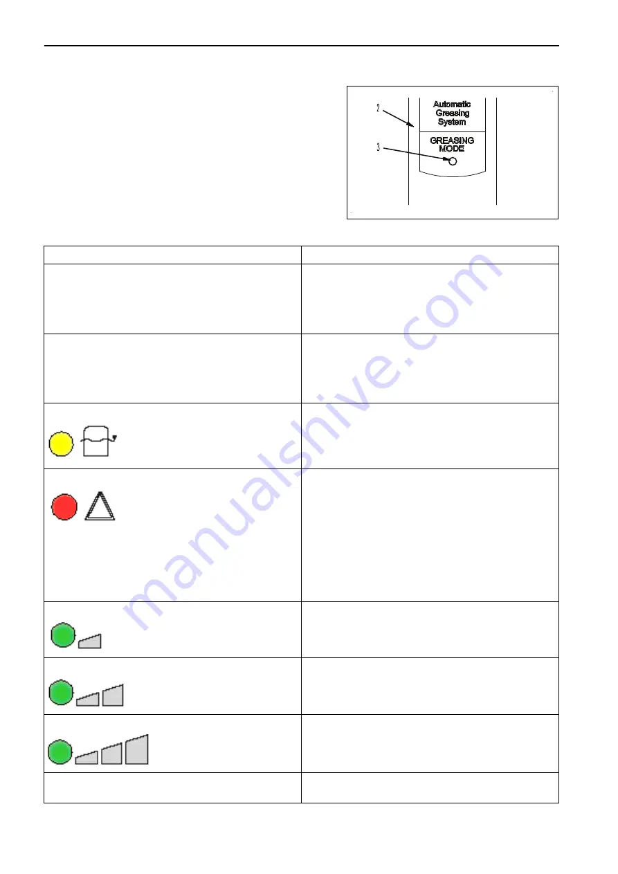
2.
Select the interval by pushing button (3) on the in-cab dis-
play (2).
INDICATION ON THE IN-CAB DISPLAY
Indication
Meaning
The red lamp (6) flashes as soon as the ignition has been
switched on.
1. The pump is not powered. Check fuses and connec-
tions to earth.
Immediate action required.
2. The connection between the in-cab display and pump
is defective, replace if necessary.
No lamp illuminates when the starting switch is in the ON
position.
1. The system is not powered. Check fuses and connec-
tions to earth.
Immediate action is required.
2. The display or wiring of the in-cab display is defective.
Check in-cab display and wiring and replace if necessary.
Yellow lamp (5) flashing
Minimum level in the reservoir has been reached. Reset
by filling the reservoir.
Red lamp (6) flashing
System out of order. Immediate action required.
Possible causes:
Insufficient grease pressure during 10 consecutive cycles
(or 10 consecutive times in the same main line). Check
for cause and reset by depressing the test button at the
pump for at least one second while the ignition is switch-
ed on.
Reservoir empty; reset by refilling the reservoir and after
that depressing the test button for at least one second
while the ignition is switched on.
Green lamp (4) flashing
Low duty
Green lamp (4) flashing
Normal duty
Green lamp (4) flashing
Heavy duty
A green lamp is flashing during one complete cycle (2.0
sec. on/2.0 sec. off)
Single test run being executed
KS000879
AUTOMATIC GREASE SYSTEM
ATTACHMENTS AND OPTIONS
6-10
Содержание PC210-11
Страница 2: ......
Страница 24: ......
Страница 74: ......
Страница 75: ...OPERATION Please read and make sure that you understand the SAFETY section before reading this section 3 1 ...
Страница 352: ......
Страница 353: ...MAINTENANCE Please read and make sure that you understand the SAFETY section before reading this section 4 1 ...
Страница 431: ...SPECIFICATIONS 5 1 ...
Страница 435: ...PC210LC 11 PC210NLC 11 SPECIFICATIONS SPECIFICATIONS 5 5 ...
Страница 436: ...PC230NHD 11 SPECIFICATIONS SPECIFICATIONS 5 6 ...
Страница 458: ...PC210 11 2 Piece Boom PC210LC 11 2 Piece Boom PC210NLC 11 2 Piece Boom 2 PIECE BOOM ATTACHMENTS AND OPTIONS 6 22 ...
Страница 459: ...PC230NHD 11 2 Piece Boom ATTACHMENTS AND OPTIONS 2 PIECE BOOM 6 23 ...
Страница 470: ... Not including tail swing SUPER LONG FRONT BOOM AND ARM ATTACHMENTS AND OPTIONS 6 34 ...
Страница 505: ...REPLACEMENT PARTS 7 1 ...
Страница 521: ......


