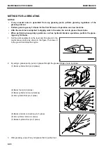
METHOD FOR BLEEDING AIR FROM ATTACHMENT (WHEN ATTACHMENT IS
EQUIPPED)
NOTICE
• If the method of air bleeding from the attachment is specified by the manufacturer, bleed the air ac-
cording to the specified procedure.
• After completing the air bleeding operation, stop the engine, and leave the machine for 5 minutes
before starting operations. This will remove the air bubbles in the oil inside the hydraulic tank.
• Immediately after the attachment is replaced, air can be mixed into the attachment 2 variable relief
pressure valve, and the pulsation of drain hose can occur. This will be solved by a complete air
bleeding.
If a breaker or other attachment is installed, perform the air bleeding procedure until the air is completely bled
from the attachment circuit.
1.
Turn the fuel control dial to Low idle (MIN) position.
2.
Repeat operating the attachment approximately 10 times to bleed air.
3.
Check that there is no leakage of oil and wipe off any oil that is spilled.
4.
After completing the air bleeding operation, check the oil level, and if the oil level is low, add oil.
METHOD FOR CHECKING CAMERA VISIBILITY
The direction of camera may be changed by a shock to the camera. Check the visibility of the camera.
Put a traffic cone on a stand at the position approximately 1 m
(A) rearward from the rear end of the machine and approxi-
mately 1 m (B) outside from the centerline of a track, so that
the traffic cone is at the height approximately 70 cm (C).
If the traffic cone can be seen on the monitor screen, it is nor-
mal.
If the traffic cone cannot be seen on the monitor screen, ask your Komatsu distributor for adjustment of the cam-
era image.
CHECK AUTOMATIC GREASE SYSTEM
PERIODIC CHECKS
1.
Check the grease level in the reservoir, but do not refill the reservoir before minimum level is reached.
2.
Check the in-cab display is functioning.
3.
Check if the selected interval time is correct for the working conditions of the machine.
4.
Check the pump for damage and leakage.
5.
Check the grease pipes for damage and leakage.
MAINTENANCE PROCEDURE
MAINTENANCE
4-38
Содержание PC210-11
Страница 2: ......
Страница 24: ......
Страница 74: ......
Страница 75: ...OPERATION Please read and make sure that you understand the SAFETY section before reading this section 3 1 ...
Страница 352: ......
Страница 353: ...MAINTENANCE Please read and make sure that you understand the SAFETY section before reading this section 4 1 ...
Страница 431: ...SPECIFICATIONS 5 1 ...
Страница 435: ...PC210LC 11 PC210NLC 11 SPECIFICATIONS SPECIFICATIONS 5 5 ...
Страница 436: ...PC230NHD 11 SPECIFICATIONS SPECIFICATIONS 5 6 ...
Страница 458: ...PC210 11 2 Piece Boom PC210LC 11 2 Piece Boom PC210NLC 11 2 Piece Boom 2 PIECE BOOM ATTACHMENTS AND OPTIONS 6 22 ...
Страница 459: ...PC230NHD 11 2 Piece Boom ATTACHMENTS AND OPTIONS 2 PIECE BOOM 6 23 ...
Страница 470: ... Not including tail swing SUPER LONG FRONT BOOM AND ARM ATTACHMENTS AND OPTIONS 6 34 ...
Страница 505: ...REPLACEMENT PARTS 7 1 ...
Страница 521: ......


