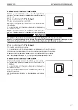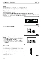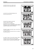
(J) Switch F5: Cancels any change and returns the screen to
the previous screen.
(K) Switch F6: Enters the selection and contents to change,
and proceeds the screen to the next screen.
REMARK
• Even if some icons look the same, their display positions
and corresponding function switches may differ according
to the screens to be displayed.
• For the guidance icons and their functions not explained
above, see the pages where the control methods of re-
spective screens are explained.
WORKING MODE SELECTOR SWITCH
Use working mode selector switch (1) to set the movement or
power of the work equipment.
The operation becomes easier by selecting the mode to match
the content of the operation.
P mode: For heavy-duty operations
E mode: For operations with emphasis on fuel consumption
L mode: For fine control operations and lifting operations
B mode: For breaker operations
ATT/P mode: For operations of 2-way attachments like crusher
(machines ready for installation of attachment)
ATT/E mode: For operations emphasizing fuel consumption out
of those of 2-way attachments like crusher (machines ready
for installation of attachment)
• When the monitor is turned ON, it is automatically set to
the mode used when the starting switch was turned to
OFF position last.
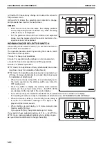
• Press the switch to display the working mode selection
screen (2). For each set mode, P, E, L, B, ATT/P, ATT/E
are displayed at the top right of the monitor display.
• For machines ready for installation of attachment, the attachment mode is added to the display.
For handling of machines ready for installation of attachment, see “ATTACHMENTS AND OPTIONS”.
• When the monitor starts up, if the working mode setting is
B mode, the confirmation message in the figure is dis-
played and the buzzer sounds.
• When starting up and staying in B mode, always press
function switch F6 (Yes).
If you press F5 (No), the system starts up in E mode.
If you want to have automatic setting of P, E, L, B, ATT/P or
ATT/E mode (optional default setting) when starting engine ,
ask your Komatsu distributor to change the setting.
EXPLANATION OF COMPONENTS
OPERATION
3-44
Содержание PC210-11
Страница 2: ......
Страница 24: ......
Страница 74: ......
Страница 75: ...OPERATION Please read and make sure that you understand the SAFETY section before reading this section 3 1 ...
Страница 352: ......
Страница 353: ...MAINTENANCE Please read and make sure that you understand the SAFETY section before reading this section 4 1 ...
Страница 431: ...SPECIFICATIONS 5 1 ...
Страница 435: ...PC210LC 11 PC210NLC 11 SPECIFICATIONS SPECIFICATIONS 5 5 ...
Страница 436: ...PC230NHD 11 SPECIFICATIONS SPECIFICATIONS 5 6 ...
Страница 458: ...PC210 11 2 Piece Boom PC210LC 11 2 Piece Boom PC210NLC 11 2 Piece Boom 2 PIECE BOOM ATTACHMENTS AND OPTIONS 6 22 ...
Страница 459: ...PC230NHD 11 2 Piece Boom ATTACHMENTS AND OPTIONS 2 PIECE BOOM 6 23 ...
Страница 470: ... Not including tail swing SUPER LONG FRONT BOOM AND ARM ATTACHMENTS AND OPTIONS 6 34 ...
Страница 505: ...REPLACEMENT PARTS 7 1 ...
Страница 521: ......


