METHOD FOR STARTING ENGINE
1.
Check both of normal machine and failed machine that the lock lever is set to LOCK position.
Check also that all the control levers are in NEUTRAL position.
2.
Make sure the clips are firmly connected to the battery terminals.
3.
Start the engine of the normal machine and run it at high idle (max. speed).
4.
Turn the starting switch of the failed machine to START position and start the engine.
If the engine does not start, try again after at least 2 minutes.
PROCEDURE FOR REMOVING JUMPER CABLE
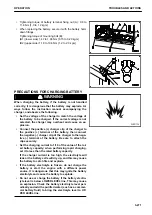
After the engine has started, disconnect the jumper cables in the reverse of the order in which they were con-
nected.
1.
Remove the clip of jumper cable (B) from the revolving
frame (E) of the failed machine.
2.
Remove the clip of jumper cable (B) from the negative (-)
terminal of battery (D) on the normal machine.
3.
Remove the clip of jumper cable (A) from the positive (+)
terminal of battery (D) on the normal machine.
4.
Remove the clip of jumper cable (A) from the positive (+)
terminal of battery (C) on the failed machine.
OTHER TROUBLE
PHENOMENA AND ACTIONS FOR ELECTRICAL SYSTEM
• For the remedies indicated with (*) in the remedy column, always contact your Komatsu distributor.
• In cases of problems or causes which are not listed below, ask your Komatsu distributor for repairs.
Problem
Main causes
Remedy
Lamp does not glow brightly even
when the engine runs at high
speeds.
Defective wiring, deterioration of bat-
tery
Check and repair loose terminal or
wire breakage, replace battery. (*)
Loosening and damage of fan belt
Check fan belt tension and replace.
(*)
Lamp flickers while engine is run-
ning.
Defective wiring, deterioration of bat-
tery
Check and repair loose terminal or
wire breakage, replace battery. (*)
Loosening and damage of fan belt
Check fan belt tension and replace.
(*)
Charge level caution lamp does not
go out even when engine is running.
Defective alternator
Replace. (*)
Defective wiring
Check, repair. (*)
Loose fan belt
Check fan belt tension and replace.
(*)
Unusual noise is generated from al-
ternator
Defective alternator
Replace. (*)
OPERATION
TROUBLES AND ACTIONS
3-273
Содержание PC210-11
Страница 2: ......
Страница 24: ......
Страница 74: ......
Страница 75: ...OPERATION Please read and make sure that you understand the SAFETY section before reading this section 3 1 ...
Страница 352: ......
Страница 353: ...MAINTENANCE Please read and make sure that you understand the SAFETY section before reading this section 4 1 ...
Страница 431: ...SPECIFICATIONS 5 1 ...
Страница 435: ...PC210LC 11 PC210NLC 11 SPECIFICATIONS SPECIFICATIONS 5 5 ...
Страница 436: ...PC230NHD 11 SPECIFICATIONS SPECIFICATIONS 5 6 ...
Страница 458: ...PC210 11 2 Piece Boom PC210LC 11 2 Piece Boom PC210NLC 11 2 Piece Boom 2 PIECE BOOM ATTACHMENTS AND OPTIONS 6 22 ...
Страница 459: ...PC230NHD 11 2 Piece Boom ATTACHMENTS AND OPTIONS 2 PIECE BOOM 6 23 ...
Страница 470: ... Not including tail swing SUPER LONG FRONT BOOM AND ARM ATTACHMENTS AND OPTIONS 6 34 ...
Страница 505: ...REPLACEMENT PARTS 7 1 ...
Страница 521: ......


