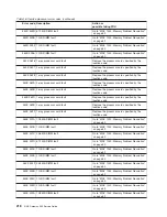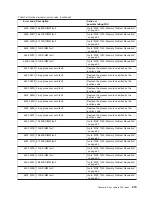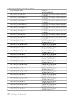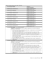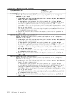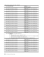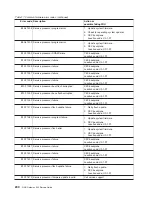
Table 17. Common firmware error codes (continued)
Error code Description
Action or
possible failing FRU
B1xx 4620 Modem configuration failure
1. Check modem configuration files.
2. Check for system firmware update.
3. Modem
4. CEC backplane
Location code: U0.1-P1
B1xx 4621 Modem disconnect failure
1. Check modem configuration files.
2. Check for system firmware update.
3. Modem
4. CEC backplane
Location code: U0.1-P1
B1xx 4622 Service processor failure
1. Operator panel
Location code: U0.1-L1
2. Check for system firmware update.
3. CEC backplane
Location code: U0.1-P1
B1xx 4633 System power control network failure
1. Check for system firmware update.
2. CEC backplane
Location code: U0.1-P1
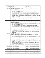
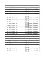
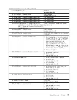
B1xx 4634 SPCN loop fault
Go to “MAP 1540: Problem Isolation Procedures”
on page 69.
B1xx 4643 I2C card/flex cable detection error
Go to “MAP 1540: Problem Isolation Procedures”
on page 69.
B1xx 4644 Processor VPD system fault
Go to “MAP 1540: Problem Isolation Procedures”
on page 69.
B1xx 4645 I2C (Non-processor) VPD System Fault
Go to “MAP 1540: Problem Isolation Procedures”
on page 69.
B1xx 4646 General VPD fault
Go to “MAP 1540: Problem Isolation Procedures”
on page 69.
B1xx 4647 Write TM field in system VPD
Replace the operator panel, location: U0.1-L1.
Do not swap the VPD module from the old
operator panel onto the new operator panel;
leave the new, unprogrammed VPD module on
the new operator panel. Call service support for
instructions.
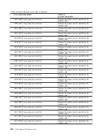
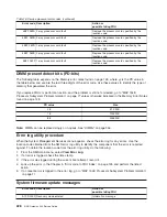
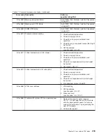
B1xx 4648 CPU Backplane VPD or Power Source
Go to “MAP 1540: Problem Isolation Procedures”
on page 69.
B1xx 4649 Power supply VPD failure
CEC power supply
Location code: U0.1-V1, U0.1-V2
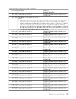
B1xx 4650 A system processor failure has been detected by
the service processor. All system processors
have been reset in an attempt to recover
operations.
Information only. If the problem persists, check
the error logs for other fault indications.
If no other fault indications are found, go to
“MAP 1540: Problem Isolation Procedures” on
page 69.
B1xx 4651 CPU VPD fault
Processor card
Location code: U0.1-P1-C1, U0.1-P1-C2
232
NAS Gateway 500 Service Guide
Содержание TotalStorage NAS Gateway 500
Страница 1: ...IBM TotalStorage NAS Gateway 500 Service Guide GY27 0418 00 ...
Страница 2: ......
Страница 3: ...IBM TotalStorage NAS Gateway 500 Service Guide GY27 0418 00 ...
Страница 16: ...xiv NAS Gateway 500 Service Guide ...
Страница 20: ...xviii NAS Gateway 500 Service Guide ...
Страница 36: ...System logic flow Note Not all components are supported 16 NAS Gateway 500 Service Guide ...
Страница 52: ...32 NAS Gateway 500 Service Guide ...
Страница 58: ...38 NAS Gateway 500 Service Guide ...
Страница 68: ...Step 0410 13 This completes the repair return the system to the user 48 NAS Gateway 500 Service Guide ...
Страница 112: ...92 NAS Gateway 500 Service Guide ...
Страница 266: ...246 NAS Gateway 500 Service Guide ...
Страница 326: ...306 NAS Gateway 500 Service Guide ...
Страница 353: ...Chapter 11 Removal and replacement procedures 333 ...
Страница 392: ...372 NAS Gateway 500 Service Guide ...
Страница 394: ...System parts 1 5 6 9 10 11 12 8 7 13 4 15 16 17 18 19 20 14 3 2 374 NAS Gateway 500 Service Guide ...
Страница 396: ...System parts continued 1 12 13 3 10 12 8 15 14 14 16 18 19 17 7 9 11 4 4 5 6 2 376 NAS Gateway 500 Service Guide ...
Страница 402: ...382 NAS Gateway 500 Service Guide ...
Страница 412: ...392 NAS Gateway 500 Service Guide ...
Страница 440: ...420 NAS Gateway 500 Service Guide ...
Страница 446: ...426 NAS Gateway 500 Service Guide ...
Страница 448: ...428 NAS Gateway 500 Service Guide ...
Страница 466: ...446 NAS Gateway 500 Service Guide ...
Страница 469: ......
Страница 470: ... Printed in U S A GY27 0418 00 ...
Страница 471: ...Spine information IBM TotalStorage NAS Gateway 500 NAS Gateway 500 Service Guide GY27 0418 00 ...

