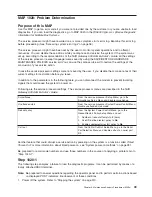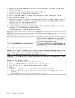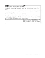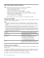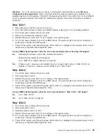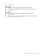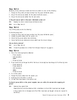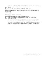
Does the power LED on the operator panel come on and stay on?
NO
Reinstall the original FRU.
Repeat this step until the defective FRU is identified or all the FRUs have been exchanged.
If the symptom did not change and all the FRUs have been exchanged, call service support for
assistance.
YES
Go to “MAP 0410: Repair Checkout” on page 45.
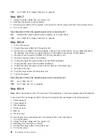
Step 1521-10
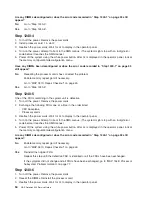
One of the parts that was removed or unplugged is causing the problem. Install or connect the parts in the
following order:
1. DIMMs on processor card #1
2. Processor book #2 (if removed)
3. DASD backplane
4. Disk drives
5. Media bay devices
6. PCI adapters, lowest slot to highest slot
7. Fans
Turn on the power after each part is installed or connected. If the system does not power on or the power
LED located on the operator panel does not stay on, the most recently installed or connected part is
causing the failure.
Do the following as you exchange each of the above FRUs in the order listed.
1. Turn off the power.
2. Unplug the power cables from the system unit.
3. Install or connect one of the parts in the list.
4. Plug the power cables into the system unit.
5. Turn on the power.
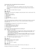
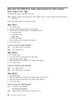
Does the power LED on the operator panel come on and stay on?
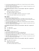
NO
Replace the last part installed.
v
If DIMMs on the first processor card were the last parts installed, exchange the DIMMs one at a
time to isolate the failing module. If all DIMMs have been exchanged and the problem is not
resolved, replace the processor card.
v
If the second processor card was just installed, exchange the DIMMs one at a time to isolate a
possible failing module. If all modules have been exchanged and the problem is not resolved,
replace the processor card.
Repeat these steps until all the parts have been installed. Go to “Step 1521-11”.
YES
Go to “MAP 0410: Repair Checkout” on page 45.
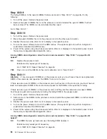
Step 1521-11
Does the system contain two power supplies?
NO
Go to “Step 1521-12”.
YES
Go to “Step 1521-14” on page 64.
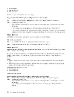
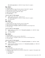
Step 1521-12
Shut down the system and remove all power cables from the back of the system unit.
Exchange the following FRUs in the order listed:
Chapter 3. Maintenance Analysis Procedures (MAPs)
63
Содержание TotalStorage NAS Gateway 500
Страница 1: ...IBM TotalStorage NAS Gateway 500 Service Guide GY27 0418 00 ...
Страница 2: ......
Страница 3: ...IBM TotalStorage NAS Gateway 500 Service Guide GY27 0418 00 ...
Страница 16: ...xiv NAS Gateway 500 Service Guide ...
Страница 20: ...xviii NAS Gateway 500 Service Guide ...
Страница 36: ...System logic flow Note Not all components are supported 16 NAS Gateway 500 Service Guide ...
Страница 52: ...32 NAS Gateway 500 Service Guide ...
Страница 58: ...38 NAS Gateway 500 Service Guide ...
Страница 68: ...Step 0410 13 This completes the repair return the system to the user 48 NAS Gateway 500 Service Guide ...
Страница 112: ...92 NAS Gateway 500 Service Guide ...
Страница 266: ...246 NAS Gateway 500 Service Guide ...
Страница 326: ...306 NAS Gateway 500 Service Guide ...
Страница 353: ...Chapter 11 Removal and replacement procedures 333 ...
Страница 392: ...372 NAS Gateway 500 Service Guide ...
Страница 394: ...System parts 1 5 6 9 10 11 12 8 7 13 4 15 16 17 18 19 20 14 3 2 374 NAS Gateway 500 Service Guide ...
Страница 396: ...System parts continued 1 12 13 3 10 12 8 15 14 14 16 18 19 17 7 9 11 4 4 5 6 2 376 NAS Gateway 500 Service Guide ...
Страница 402: ...382 NAS Gateway 500 Service Guide ...
Страница 412: ...392 NAS Gateway 500 Service Guide ...
Страница 440: ...420 NAS Gateway 500 Service Guide ...
Страница 446: ...426 NAS Gateway 500 Service Guide ...
Страница 448: ...428 NAS Gateway 500 Service Guide ...
Страница 466: ...446 NAS Gateway 500 Service Guide ...
Страница 469: ......
Страница 470: ... Printed in U S A GY27 0418 00 ...
Страница 471: ...Spine information IBM TotalStorage NAS Gateway 500 NAS Gateway 500 Service Guide GY27 0418 00 ...

