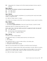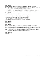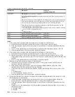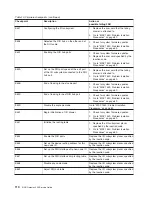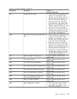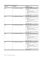
d. If this procedure does not fix the problem, call service support.
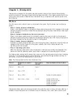
Firmware checkpoints
Firmware uses checkpoints (progress codes) in the range of Exxx to EFFF. These checkpoints occur
during system startup and can be useful in diagnosing certain problems. Service processor checkpoints
are listed in “Service processor checkpoints” on page 94.
If you have a checkpoint with no location code associated with it, see “Determining location code” on
page 126. If a checkpoint has a location code associated with a FRU replacement, see “Mapping AIX and
physical location codes” on page 21 for physical location information.
If you replace FRUs and the problem is still not corrected, go to “MAP 1548: Processor Subsystem
Problem Isolation” on page 77 unless otherwise indicated in the tables.
Notes:
1. If you receive a four-digit code in the range of E1xx to EFFF that is not listed in the following table, go
to “MAP 1548: Processor Subsystem Problem Isolation” on page 77.
2. Not all firmware checkpoints are supported.
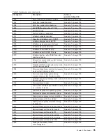
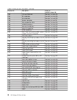
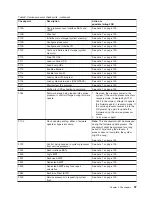
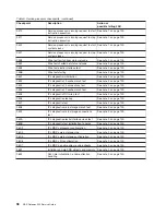
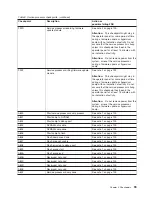
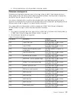
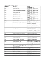
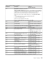
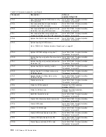
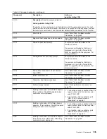
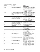
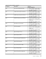
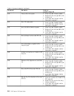
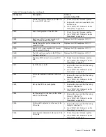
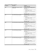
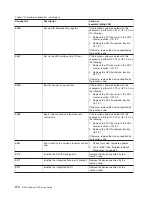
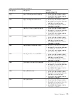
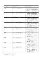
Table 10. Firmware checkpoints
Checkpoint
Description
Action or
possible failing FRU
E101
Create RTAS node
Go to “MAP 1540: Problem Isolation
Procedures” on page 69.
E102
Load/Init RTAS
Go to “MAP 1540: Problem Isolation
Procedures” on page 69.
E105
Transfer control to operating system
(normal boot).
See “Boot problems or concerns” on
page 122.
E10A
Load RTAS device tree
Go to “MAP 1540: Problem Isolation
Procedures” on page 69.
E10B
Set RTAS device properties
Go to “MAP 1540: Problem Isolation
Procedures” on page 69.
E111
GOOD CRC - jump to composite image
Go to “MAP 1540: Problem Isolation
Procedures” on page 69.
E120
Initialize I/O and early memory block
Go to “MAP 1540: Problem Isolation
Procedures” on page 69.
E121
Initialize service processor
Go to “MAP 1540: Problem Isolation
Procedures” on page 69.
E122
RTAS sensor setup complete
Go to “MAP 1540: Problem Isolation
Procedures” on page 69.
E130
Build device tree
Go to “MAP 1540: Problem Isolation
Procedures” on page 69.
E131
Build device tree
Go to “MAP 1540: Problem Isolation
Procedures” on page 69.
E132
Build device tree
Go to “MAP 1540: Problem Isolation
Procedures” on page 69.
E133
Build device tree
Go to “MAP 1540: Problem Isolation
Procedures” on page 69.
E134
Create memory node
Go to “MAP 1540: Problem Isolation
Procedures” on page 69.
Chapter 4. Checkpoints
101
Содержание TotalStorage NAS Gateway 500
Страница 1: ...IBM TotalStorage NAS Gateway 500 Service Guide GY27 0418 00 ...
Страница 2: ......
Страница 3: ...IBM TotalStorage NAS Gateway 500 Service Guide GY27 0418 00 ...
Страница 16: ...xiv NAS Gateway 500 Service Guide ...
Страница 20: ...xviii NAS Gateway 500 Service Guide ...
Страница 36: ...System logic flow Note Not all components are supported 16 NAS Gateway 500 Service Guide ...
Страница 52: ...32 NAS Gateway 500 Service Guide ...
Страница 58: ...38 NAS Gateway 500 Service Guide ...
Страница 68: ...Step 0410 13 This completes the repair return the system to the user 48 NAS Gateway 500 Service Guide ...
Страница 112: ...92 NAS Gateway 500 Service Guide ...
Страница 266: ...246 NAS Gateway 500 Service Guide ...
Страница 326: ...306 NAS Gateway 500 Service Guide ...
Страница 353: ...Chapter 11 Removal and replacement procedures 333 ...
Страница 392: ...372 NAS Gateway 500 Service Guide ...
Страница 394: ...System parts 1 5 6 9 10 11 12 8 7 13 4 15 16 17 18 19 20 14 3 2 374 NAS Gateway 500 Service Guide ...
Страница 396: ...System parts continued 1 12 13 3 10 12 8 15 14 14 16 18 19 17 7 9 11 4 4 5 6 2 376 NAS Gateway 500 Service Guide ...
Страница 402: ...382 NAS Gateway 500 Service Guide ...
Страница 412: ...392 NAS Gateway 500 Service Guide ...
Страница 440: ...420 NAS Gateway 500 Service Guide ...
Страница 446: ...426 NAS Gateway 500 Service Guide ...
Страница 448: ...428 NAS Gateway 500 Service Guide ...
Страница 466: ...446 NAS Gateway 500 Service Guide ...
Страница 469: ......
Страница 470: ... Printed in U S A GY27 0418 00 ...
Страница 471: ...Spine information IBM TotalStorage NAS Gateway 500 NAS Gateway 500 Service Guide GY27 0418 00 ...

