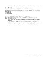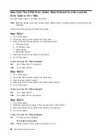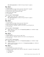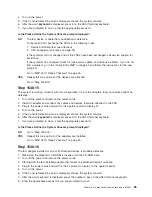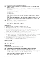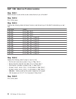
10. Remove processor card #2 (if installed). If processor card #2 is removed, ensure that processor card
#1 is installed and contains at least one quad of DIMMs.
The processor card that is left in the system must contain at least one quad of DIMMs. For example,
with a system configuration having two processor cards, processor card #2 contains all of the DIMMs,
processor card #1 contains no DIMMs. Remove processor card #1 that contains no DIMMs, and then
remove all but one quad of DIMMs from processor card #2. Place processor card #2 into processor
slot #1.
11. Record the slot numbers of the DIMMs on processor card #1. Remove all DIMMs except for one quad
from processor card #1.
Notes:
a. Place the DIMM locking tabs in the locked (upright) position to prevent damage to the tabs.
b. DIMMs must be installed in quads and in the correct connectors. Refer to “DIMM locations” on
page 12 for complete information on DIMMs.
12. Disconnect the cables attached to the PCI riser card.
13. Disconnect the IDE cable from the IDE connector on the CEC backplane.
14. If your system is equipped with a diskette drive, disconnect the diskette drive cable from the diskette
drive connector on the CEC backplane.
15. Disconnect the signal and power connectors from the disk drive backplane.
16. Disconnect the disk drives from the disk drive backplane connectors.
17. Reinstall the media tray.
18. Plug in the power cords and wait for the operator panel to display
OK
.
19. Turn on the power.
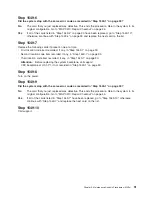
Does the system stop with code E1F2, E1F3, STBY or 20EE000B, 4BA00830 displayed on the
operator panel?
NO
Go to “Step 1548-6” on page 80.
YES
Go to “Step 1548-3”.
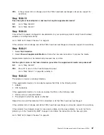
Step 1548-3
Were any more DIMMs removed from processor card #1?
NO
Go to “Step 1548-5” on page 80.
YES
Go to “Step 1548-4”.
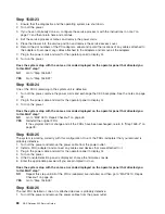
Step 1548-4
1. Turn off the power, and remove the power cords.
2. Replug the DIMMs that were removed from processor #1 in “Step 1548-2” on page 78 in their original
locations.
Notes:
a. Place the DIMM locking tabs into the locked (upright) position to prevent damage to the tabs.
b. DIMMs must be installed in quads in the correct connectors. Refer to “DIMM locations” on page 12
for complete information on DIMMs.
3. Plug in the power cords and wait for the operator panel to display
OK
.
4. Turn on the power.
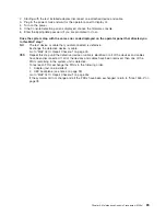
Chapter 3. Maintenance Analysis Procedures (MAPs)
79
Содержание TotalStorage NAS Gateway 500
Страница 1: ...IBM TotalStorage NAS Gateway 500 Service Guide GY27 0418 00 ...
Страница 2: ......
Страница 3: ...IBM TotalStorage NAS Gateway 500 Service Guide GY27 0418 00 ...
Страница 16: ...xiv NAS Gateway 500 Service Guide ...
Страница 20: ...xviii NAS Gateway 500 Service Guide ...
Страница 36: ...System logic flow Note Not all components are supported 16 NAS Gateway 500 Service Guide ...
Страница 52: ...32 NAS Gateway 500 Service Guide ...
Страница 58: ...38 NAS Gateway 500 Service Guide ...
Страница 68: ...Step 0410 13 This completes the repair return the system to the user 48 NAS Gateway 500 Service Guide ...
Страница 112: ...92 NAS Gateway 500 Service Guide ...
Страница 266: ...246 NAS Gateway 500 Service Guide ...
Страница 326: ...306 NAS Gateway 500 Service Guide ...
Страница 353: ...Chapter 11 Removal and replacement procedures 333 ...
Страница 392: ...372 NAS Gateway 500 Service Guide ...
Страница 394: ...System parts 1 5 6 9 10 11 12 8 7 13 4 15 16 17 18 19 20 14 3 2 374 NAS Gateway 500 Service Guide ...
Страница 396: ...System parts continued 1 12 13 3 10 12 8 15 14 14 16 18 19 17 7 9 11 4 4 5 6 2 376 NAS Gateway 500 Service Guide ...
Страница 402: ...382 NAS Gateway 500 Service Guide ...
Страница 412: ...392 NAS Gateway 500 Service Guide ...
Страница 440: ...420 NAS Gateway 500 Service Guide ...
Страница 446: ...426 NAS Gateway 500 Service Guide ...
Страница 448: ...428 NAS Gateway 500 Service Guide ...
Страница 466: ...446 NAS Gateway 500 Service Guide ...
Страница 469: ......
Страница 470: ... Printed in U S A GY27 0418 00 ...
Страница 471: ...Spine information IBM TotalStorage NAS Gateway 500 NAS Gateway 500 Service Guide GY27 0418 00 ...

