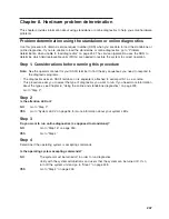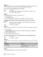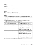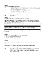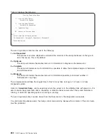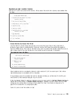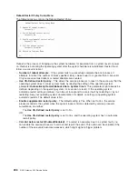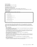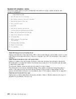
Chapter 9. Using the service processor
Note:
The information in this chapter regarding the configuring of serial ports (and modems attached to
those serial ports), applies only to serial port 1 and 2 on the CEC backplane (location U0.1-P1).
The service processor runs on its own power boundary and continually monitors hardware attributes and
the environmental conditions within the system. The service processor is controlled by firmware and does
not require the operating system to be operational to perform its tasks.
The service processor menus allow you to configure service processor options, as well as enable and
disable functions.
Service processor menus are available using an ASCII terminal when
OK
is displayed on the operator
panel or when the service processor has detected a system problem (such as a surveillance failure).
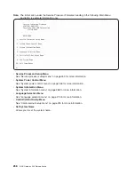
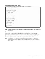
Service processor menus
The service processor menus are divided into the following groups:
v
General user menu - the user must know the general-access password.
v
Privileged user menus - the user must know the privileged-access password.
If the system is powered off, the service processor menus can be accessed locally on serial port 1 (S1) or
remotely using a modem on serial port 2 (S2).
The service processor menu prompt, represented by
0>
or
1>
, indicates the serial port to which the
terminal is connected. A terminal can have the following prompts:
v
0>
indicates serial port 1 (S1)
v
1>
indicates serial port 2 (S2)
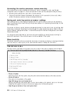
Accessing the service processor menus locally
Service processor menus can be accessed by attaching an ASCII terminal to serial port 1 (S1). After
OK
is
displayed in the operator panel, press any key on the keyboard to signal the service processor.
When you gain access, the service processor prompts you for a password (if one is set) and, when
verified, displays the service processor menus.
255
Содержание TotalStorage NAS Gateway 500
Страница 1: ...IBM TotalStorage NAS Gateway 500 Service Guide GY27 0418 00 ...
Страница 2: ......
Страница 3: ...IBM TotalStorage NAS Gateway 500 Service Guide GY27 0418 00 ...
Страница 16: ...xiv NAS Gateway 500 Service Guide ...
Страница 20: ...xviii NAS Gateway 500 Service Guide ...
Страница 36: ...System logic flow Note Not all components are supported 16 NAS Gateway 500 Service Guide ...
Страница 52: ...32 NAS Gateway 500 Service Guide ...
Страница 58: ...38 NAS Gateway 500 Service Guide ...
Страница 68: ...Step 0410 13 This completes the repair return the system to the user 48 NAS Gateway 500 Service Guide ...
Страница 112: ...92 NAS Gateway 500 Service Guide ...
Страница 266: ...246 NAS Gateway 500 Service Guide ...
Страница 326: ...306 NAS Gateway 500 Service Guide ...
Страница 353: ...Chapter 11 Removal and replacement procedures 333 ...
Страница 392: ...372 NAS Gateway 500 Service Guide ...
Страница 394: ...System parts 1 5 6 9 10 11 12 8 7 13 4 15 16 17 18 19 20 14 3 2 374 NAS Gateway 500 Service Guide ...
Страница 396: ...System parts continued 1 12 13 3 10 12 8 15 14 14 16 18 19 17 7 9 11 4 4 5 6 2 376 NAS Gateway 500 Service Guide ...
Страница 402: ...382 NAS Gateway 500 Service Guide ...
Страница 412: ...392 NAS Gateway 500 Service Guide ...
Страница 440: ...420 NAS Gateway 500 Service Guide ...
Страница 446: ...426 NAS Gateway 500 Service Guide ...
Страница 448: ...428 NAS Gateway 500 Service Guide ...
Страница 466: ...446 NAS Gateway 500 Service Guide ...
Страница 469: ......
Страница 470: ... Printed in U S A GY27 0418 00 ...
Страница 471: ...Spine information IBM TotalStorage NAS Gateway 500 NAS Gateway 500 Service Guide GY27 0418 00 ...

