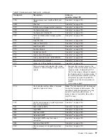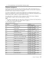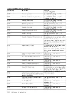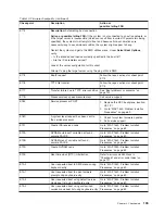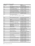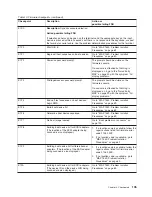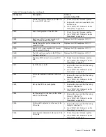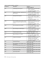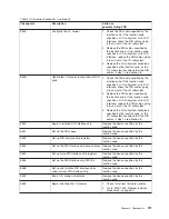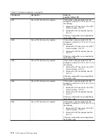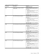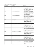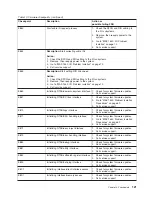
Table 10. Firmware checkpoints (continued)
Checkpoint
Description
Action or
possible failing FRU
E54A
Configure the I/O drawer
1. Check the RIO cable specified by the
location code. If the location code
specifies an I/O subsystem or its RIO
interface, check the RIO cables going
into and out of the I/O subsystem.
2. Replace the RIO cables specified by
the location code. If the location code
specifies an I/O subsystem or its RIO
interface, replace the RIO cables going
into and out of the I/O subsystem.
3. Replace the I/O subsystem backplane
specified by the location code, or the
I/O subsystem backplane that the RIO
cables in step 1 are attached to.
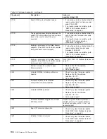
E54B
Update the I/O drawer routing table of RIO
ports
1. Check the RIO cable specified by the
location code. If the location code
specifies an I/O subsystem or its RIO
interface, check the RIO cables going
into and out of the I/O subsystem.
2. Replace the RIO cables specified by
the location code. If the location code
specifies an I/O subsystem or its RIO
interface, replace the RIO cables going
into and out of the I/O subsystem.
3. Replace the I/O subsystem backplane
specified by the location code, or the
I/O subsystem backplane that the RIO
cables in step 1 are attached to.
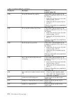
E550
Begin to initialize RIO interface chip
Replace the device specified by the
location code.
E551
Set up the RIO speed
Replace the device specified by the
location code.
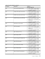
E552
Set up RIO interface chip registers
Replace the device specified by the
location code.
E553
Set up the RIO interface chip base address Replace the device specified by the
location code.
E554
Set up more RIO interface chip registers
Replace the device specified by the
location code.
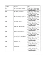
E555
Set up the RIO interface chip RIO link
Replace the device specified by the
location code.
E556
Set up and initialize RIO interface chips
under current RIO interface chip
Replace the device specified by the
location code.
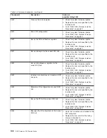
E55F
End of I/O drawer initialization
Replace the device specified by the
location code.
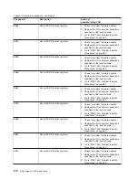
E560
Begin initializing the I/O drawer
1. Check for system firmware updates.
2. Go to “MAP 1540: Problem Isolation
Procedures” on page 69.
Chapter 4. Checkpoints
111
Содержание TotalStorage NAS Gateway 500
Страница 1: ...IBM TotalStorage NAS Gateway 500 Service Guide GY27 0418 00 ...
Страница 2: ......
Страница 3: ...IBM TotalStorage NAS Gateway 500 Service Guide GY27 0418 00 ...
Страница 16: ...xiv NAS Gateway 500 Service Guide ...
Страница 20: ...xviii NAS Gateway 500 Service Guide ...
Страница 36: ...System logic flow Note Not all components are supported 16 NAS Gateway 500 Service Guide ...
Страница 52: ...32 NAS Gateway 500 Service Guide ...
Страница 58: ...38 NAS Gateway 500 Service Guide ...
Страница 68: ...Step 0410 13 This completes the repair return the system to the user 48 NAS Gateway 500 Service Guide ...
Страница 112: ...92 NAS Gateway 500 Service Guide ...
Страница 266: ...246 NAS Gateway 500 Service Guide ...
Страница 326: ...306 NAS Gateway 500 Service Guide ...
Страница 353: ...Chapter 11 Removal and replacement procedures 333 ...
Страница 392: ...372 NAS Gateway 500 Service Guide ...
Страница 394: ...System parts 1 5 6 9 10 11 12 8 7 13 4 15 16 17 18 19 20 14 3 2 374 NAS Gateway 500 Service Guide ...
Страница 396: ...System parts continued 1 12 13 3 10 12 8 15 14 14 16 18 19 17 7 9 11 4 4 5 6 2 376 NAS Gateway 500 Service Guide ...
Страница 402: ...382 NAS Gateway 500 Service Guide ...
Страница 412: ...392 NAS Gateway 500 Service Guide ...
Страница 440: ...420 NAS Gateway 500 Service Guide ...
Страница 446: ...426 NAS Gateway 500 Service Guide ...
Страница 448: ...428 NAS Gateway 500 Service Guide ...
Страница 466: ...446 NAS Gateway 500 Service Guide ...
Страница 469: ......
Страница 470: ... Printed in U S A GY27 0418 00 ...
Страница 471: ...Spine information IBM TotalStorage NAS Gateway 500 NAS Gateway 500 Service Guide GY27 0418 00 ...

