Media drives (diskette and CD-ROM)
Note:
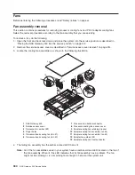
The two media bays are used to house an IDE CD-ROM (media bay 1) and diskette drive (media
bay 2). See the illustrations on page 338 for the location of the two media bays.
Before performing this procedure, read the following:
v
“Safety notices” on page xv
v
“Laser safety information” on page xvi
v
Before handling any card, board, or DIMM, be sure to use your electrostatic discharge strap to minimize
static-electric discharge. Refer to “Handling static-sensitive devices” on page 310.
v
The rack should be correctly stabilized and the system unit placed in the service position, as described
in “Placing the NAS Gateway 500 into the service position” on page 312.
v
These media drives are not hot-pluggable, and system power must be completely off during these
steps. This system is equipped with a second power supply. Before continuing with this procedure,
ensure that the power source to the system has been completely disconnected.
v
You must have removed the service access cover as described in “Service access cover removal” on
page 314 and the front bezel as described in “Front bezel removal” on page 315.
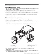
CD-ROM or diskette drive
To pull a media drive for replacement, remove the drive as described in “Media drive removal”, but leave
the media-device-support shelf in place. Then remove the four screws holding the media carrier tray to the
drive, so the tray can be used on the replacement part.
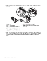
Before replacing the media drive, attach the media carrier tray to the bottom of the drive to be inserted,
with the same four screws. Place the media drive into its media bay, pushing the drive in until the release
tab clicks into the locked position. Reconnect the appropriate media signal and power cables to the drives.
Note:
The CD-ROM drive goes in center bay, and the diskette drive install in the right media bay.
Media drive removal
Some procedures require both media drives to be removed as part of other access procedures.
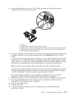
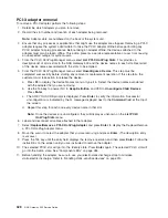
To remove the media drives located in media bay 1 and media bay 2, perform the following steps:
1. Disconnect the power and signal cables from both media devices.
2. Grasping the top front of the media device, depress the release tab located on the bottom center of the
media drive and slide the media drive out of the media bay. Repeat for the other media device.
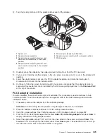
3. Remove the media-device-support shelf by loosening the thumbscrew and grasping the back edge of
the shelf, sliding it back, then lifting it up and out of the system chassis.
Note:
The support leg located on the bottom of the support shelf is used to deactivate a microswitch.
The microswitch is located on the CEC backplane and, when deactivated, cuts off power to
many of the components and connectors located on the CEC backplane. This support shelf
must be correctly seated and secured in position after any new FRU is added to the system and
before you perform a system boot.
Chapter 11. Removal and replacement procedures
337
Содержание TotalStorage NAS Gateway 500
Страница 1: ...IBM TotalStorage NAS Gateway 500 Service Guide GY27 0418 00 ...
Страница 2: ......
Страница 3: ...IBM TotalStorage NAS Gateway 500 Service Guide GY27 0418 00 ...
Страница 16: ...xiv NAS Gateway 500 Service Guide ...
Страница 20: ...xviii NAS Gateway 500 Service Guide ...
Страница 36: ...System logic flow Note Not all components are supported 16 NAS Gateway 500 Service Guide ...
Страница 52: ...32 NAS Gateway 500 Service Guide ...
Страница 58: ...38 NAS Gateway 500 Service Guide ...
Страница 68: ...Step 0410 13 This completes the repair return the system to the user 48 NAS Gateway 500 Service Guide ...
Страница 112: ...92 NAS Gateway 500 Service Guide ...
Страница 266: ...246 NAS Gateway 500 Service Guide ...
Страница 326: ...306 NAS Gateway 500 Service Guide ...
Страница 353: ...Chapter 11 Removal and replacement procedures 333 ...
Страница 392: ...372 NAS Gateway 500 Service Guide ...
Страница 394: ...System parts 1 5 6 9 10 11 12 8 7 13 4 15 16 17 18 19 20 14 3 2 374 NAS Gateway 500 Service Guide ...
Страница 396: ...System parts continued 1 12 13 3 10 12 8 15 14 14 16 18 19 17 7 9 11 4 4 5 6 2 376 NAS Gateway 500 Service Guide ...
Страница 402: ...382 NAS Gateway 500 Service Guide ...
Страница 412: ...392 NAS Gateway 500 Service Guide ...
Страница 440: ...420 NAS Gateway 500 Service Guide ...
Страница 446: ...426 NAS Gateway 500 Service Guide ...
Страница 448: ...428 NAS Gateway 500 Service Guide ...
Страница 466: ...446 NAS Gateway 500 Service Guide ...
Страница 469: ......
Страница 470: ... Printed in U S A GY27 0418 00 ...
Страница 471: ...Spine information IBM TotalStorage NAS Gateway 500 NAS Gateway 500 Service Guide GY27 0418 00 ...

