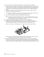
3. Lower the power supply handles, carefully pressing the power supply into the connector. The spring
latch located on the underside of each handle will snap into place, indicating that the power supply is
seated correctly and locked into position.
Note:
Improper operation of the spring-activated portion of the power supply handles can result in the
following:
v
The retractable spring remains compressed. This situation keeps the handle from locking the
power supply in its seated position. To eliminate this problem, lower the handle into the
locked position, and push the spring activated handle end toward the locking tab. This action
forces the spring latch to match with the locking tab in the spring-latch receiver hole.
v
The locking tab receiver is bent. Before lowering the handle to lock the power supply into the
seated position, ensure that the locking tab located on top of the power supply in the receiver
hole is not bent. Before the spring latch will seat onto the locking tab, the locking tab, if bent,
must be straightened.
2
3
4
1
5
6
1
Spring latch
4
Power supply
2
Spring-activated handle end
5
Spring-latch receiver hole
3
Power supply release handle
6
Locking tab
4. Plug the power cable for the added power supply into the power cable connector located on the back
of the power supply.
5. Reconnect the power source to the system. The green AC Good LED located on the power supply
should come on solid.
6. Verify that the green DC Good LED on the power supply is lit. The green LED indicates that the power
supply is operating correctly.
7.
Replace the service access cover as described in “Service access cover removal” on page 314.
8. Push the system drawer back into the operating position as described in “Returning the NAS Gateway
500 to the operating position” on page 313.
9. Close the rack doors.
Chapter 11. Removal and replacement procedures
353
Содержание TotalStorage NAS Gateway 500
Страница 1: ...IBM TotalStorage NAS Gateway 500 Service Guide GY27 0418 00 ...
Страница 2: ......
Страница 3: ...IBM TotalStorage NAS Gateway 500 Service Guide GY27 0418 00 ...
Страница 16: ...xiv NAS Gateway 500 Service Guide ...
Страница 20: ...xviii NAS Gateway 500 Service Guide ...
Страница 36: ...System logic flow Note Not all components are supported 16 NAS Gateway 500 Service Guide ...
Страница 52: ...32 NAS Gateway 500 Service Guide ...
Страница 58: ...38 NAS Gateway 500 Service Guide ...
Страница 68: ...Step 0410 13 This completes the repair return the system to the user 48 NAS Gateway 500 Service Guide ...
Страница 112: ...92 NAS Gateway 500 Service Guide ...
Страница 266: ...246 NAS Gateway 500 Service Guide ...
Страница 326: ...306 NAS Gateway 500 Service Guide ...
Страница 353: ...Chapter 11 Removal and replacement procedures 333 ...
Страница 392: ...372 NAS Gateway 500 Service Guide ...
Страница 394: ...System parts 1 5 6 9 10 11 12 8 7 13 4 15 16 17 18 19 20 14 3 2 374 NAS Gateway 500 Service Guide ...
Страница 396: ...System parts continued 1 12 13 3 10 12 8 15 14 14 16 18 19 17 7 9 11 4 4 5 6 2 376 NAS Gateway 500 Service Guide ...
Страница 402: ...382 NAS Gateway 500 Service Guide ...
Страница 412: ...392 NAS Gateway 500 Service Guide ...
Страница 440: ...420 NAS Gateway 500 Service Guide ...
Страница 446: ...426 NAS Gateway 500 Service Guide ...
Страница 448: ...428 NAS Gateway 500 Service Guide ...
Страница 466: ...446 NAS Gateway 500 Service Guide ...
Страница 469: ......
Страница 470: ... Printed in U S A GY27 0418 00 ...
Страница 471: ...Spine information IBM TotalStorage NAS Gateway 500 NAS Gateway 500 Service Guide GY27 0418 00 ...


