| Chargers |
229
1.
Secure the rubber feet to the stand with the screws.
2.
Position each stand so that its top lip is inserted into the center channel in the back of the charger.
Figure 159: Attaching the feet
Figure 160: Positioning
the stand on the charger
3.
Secure each stand to the charger by inserting screws through the holes in the stand and screwing them into the slot
on the bottom of the charger.
Figure 161: Screwing the stand into the charger
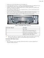
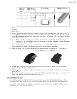
Charger Wall Mount, Multiple Chargers: T2 Series
This unit provides a convenient surface for mounting five charger units and their associated power supplies on a wall.
• Customer assembly required.
• Be aware of potential hazards (electrical wires, waterlines, etc.) when drilling the pilot holes.
• Customer assumes all responsibility for the installation of these units.
• A device charger cannot have another charger placed directly above it. A section of dry-erase board (included)
must be placed above each device charger.
• If you drill into a wall stud when drilling a pilot hole for one of the anchors, do not use an anchor with that hole.
• The lowest anchor for each extrusion must be a minimum of 12 inches from the floor.
• Avoid blocking power outlets and other wall receptacles when installing the extrusions and charger unit.
Charger Wall Mount, Multiple Chargers: Mounting the Extrusions
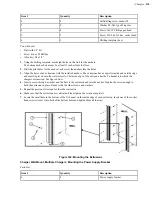
Parts List:
Item #
Quantity
Description
1
2
Extrusion
Содержание Vocollect
Страница 1: ...Honeywell Vocollect Hardware Reference ...
Страница 2: ......
Страница 4: ......
Страница 12: ......
Страница 20: ......
Страница 36: ......
Страница 80: ......
Страница 106: ......
Страница 128: ......
Страница 148: ......
Страница 150: ......
Страница 154: ... Honeywell Wired Headsets 154 ...
Страница 166: ......
Страница 287: ... Honeywell Regulatory Compliance 287 Japanese Compliance Brazilian Compliance ...
Страница 308: ......
Страница 316: ... Index 316 ...


