background image

Operation - Dual Bay Loading Application Overview 

Part No.: 4418309_Rev09

 Fusion4 MSC-L

Honeywell

 Installation & Operation Manual

5 - 69

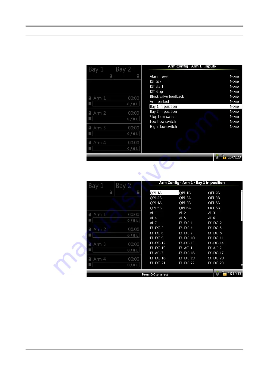
15. Select Main menu . Arm Configuration . Arm <number>. I/O bindings.

Inputs. The following screen appears.

16. On  the Arm  Configuration  . Arm  <number>  .  I/O  bindings.  Inputs

screen, select Bay 1 in position.

The following screen appears.

17. Select the required I/O binding for the selected bay.

If Bay 1 in position is Active, then the arm is in position at Bay 1; else, 

the arm is not in position at Bay 1. Similarly, if Bay 2 in position is Active, 

then the arm is in position at Bay 2; else, the arm is not in position at 

Bay 2.

Содержание Fusion4 MSC-L

Страница 1: ...Fusion4 MSC L Installation Operation Manual Fusion4 MSC L ...

Страница 2: ...For service related questions contact Technical Assistance Centre Phone 1 800 423 9883 or 1 215 641 3610 E mail HFS TAC SUPPORT honeywell com 2019 Honeywell International Inc ...

Страница 3: ...roubleshooting 2 3 2 2 4 Personal Safety 2 3 2 2 4 1 General 2 4 2 2 4 1 1 Opening the MSC L 2 4 2 2 5 Commissioning and Maintenance 2 4 2 2 5 1 Tools 2 4 2 2 6 Electrical 2 4 2 2 6 1 Grounding 2 4 2 2 7 Accordance to Regulations 2 6 2 2 7 1 Explosion Safety Limiting Values 2 6 2 2 7 2 Explosion Safety 2 6 2 2 7 3 Low Voltage Directive 2 6 2 2 7 4 The MSC L Labels 2 7 2 3 Safety Instructions for t...

Страница 4: ...w Stages 3 2 3 1 3 Types of Blending 3 3 3 1 3 1 Straight Loading 3 3 3 1 3 2 Ratio Blending 3 3 3 1 3 3 Side Stream Blending 3 3 3 1 3 4 Sequential Blending 3 4 3 1 4 Additive Injection 3 5 3 1 5 Loading Principle 3 5 3 1 5 1 Device loading capabilities 3 7 3 1 6 Menu based MSC L Control 3 8 3 2 MID Compliance 3 8 3 2 1 Introduction 3 8 3 2 2 MID Approval Approach 3 8 3 2 3 Component level Requir...

Страница 5: ...Functions 3 40 3 8 1 General 3 40 3 8 2 Digital Input DC DI DC 3 40 3 8 2 1 Functional Description 3 40 3 8 2 2 Characteristics 3 42 3 8 3 Single Pulse Input 3 42 3 8 3 1 Functional Description 3 42 3 8 3 2 Characteristics 3 44 3 8 4 Dual Pulse Input Quad PI 3 44 3 8 4 1 Functional Description 3 44 3 8 4 2 Characteristics 3 46 3 8 5 Analog Input AI 3 46 3 8 5 1 Functional Description 3 46 3 8 5 2 ...

Страница 6: ...Specifications 3 64 3 10 3 Ethernet Communication 3 64 3 10 3 1 Functional Description 3 64 3 10 3 2 Characteristics 3 65 3 10 3 3 Cable Specifications 3 65 3 11 Security Guidelines 3 66 3 11 1 Device Security Recommendations 3 66 3 11 2 Network and security control Recommendations 3 66 3 11 3 How to report a security vulnerability 3 66 CHAPTER 4 Installation 4 1 4 1 Mounting and Dimensions 4 1 4 ...

Страница 7: ...9 DC Cable 3 Gland 9 4 39 4 7 6 10 DC Cable 4 Gland 10 4 40 4 7 6 11 DC Cable 5 Gland 11 4 40 4 7 6 12 Comms Cable 1 Gland 12 4 41 4 7 6 13 DC Cable 6 Gland 13 4 41 4 7 6 14 DC Cable 7 Gland 14 4 42 4 7 6 15 Comms Cable 2 Gland 15 4 42 4 7 6 16 DC Cable 8 Gland 16 4 42 4 7 6 17 DC Cable 9 Gland 17 4 43 4 7 6 18 AC Cable 6 Gland 18 4 43 4 7 6 19 DC Cable 10 Gland 19 4 43 4 7 6 20 DC Cable 11 Gland ...

Страница 8: ...ing a Local Language Pack for the MSC L 5 15 5 3 4 5 2 Configuring a User Display Language for the MSC L 5 15 5 4 Menu and Navigation 5 15 5 4 1 General 5 15 5 4 2 Key benefits of the HMI on the Main Menu 5 16 5 4 3 Navigation Rules for the Menu based Screens 5 16 5 4 4 Main Menu 5 16 5 4 5 Stream Selection 5 17 5 4 5 1 Product Streams 5 17 5 4 5 2 Additive Streams 5 18 5 4 5 3 External Additive S...

Страница 9: ...tion 5 81 5 11 2 3 Stream Configuration Stream n 5 81 5 11 2 3 1 Stream Configuration Stream n Identification 5 81 5 11 2 3 2 Stream Configuration Stream n I O Bindings 5 82 5 11 2 3 3 Stream Configuration Stream n Control Settings 5 82 5 11 2 3 4 Stream Configuration Stream n Alarms 5 83 5 11 3 Configuring MSC L 5 83 5 11 3 1 System Configuration 5 83 5 11 3 2 External Additive Stream Configurati...

Страница 10: ...e 5 122 5 13 1 5 2 System Config Alarms Programmable Alarms 5 122 5 13 1 5 3 System Config Alarms Deadman 5 123 5 13 1 5 4 System Config Alarms Permissives 5 125 5 13 1 5 5 System Config Alarms Fixed 5 126 5 13 1 6 System Config Device Authorization 5 126 5 13 1 6 1 System Config Authorization Setup 5 127 5 13 1 6 2 System Config Authorization Databases 5 128 5 13 1 7 Device Configuration Base Con...

Страница 11: ... 5 14 2 4 Additive Stream Config Stream n Alarms 5 182 5 14 2 4 1 Leaking Valve 5 182 5 14 2 4 2 No Additive 5 183 5 14 2 4 3 No Pump 5 183 5 14 2 4 4 Block Valve Fault 5 184 5 14 2 4 5 Deviation 5 184 5 14 2 4 6 Fixed 5 185 5 14 3 Stream Configuration External Additive streams 5 186 5 14 3 1 Stream Config Ext add n Identification 5 188 5 14 3 2 Stream Config Ext add n Alarms 5 189 5 15 Arm Config...

Страница 12: ...4 Analog I O 5 230 5 17 3 System Health 5 230 5 17 4 Process Data 5 232 5 17 5 Storage Info 5 233 5 17 6 Accumulated Totals 5 233 5 17 7 Comms Info 5 241 5 17 8 Device Tasks 5 242 5 17 8 1 Reset Tasks 5 243 5 17 8 2 Execute Tasks 5 244 5 17 8 3 Clear Tasks 5 245 5 17 9 Maintenance 5 247 5 17 10 Advanced 5 249 5 18 Calibration 5 252 5 18 1 Why Calibrate 5 252 5 18 2 Calibration Menu Choice 5 255 5 ...

Страница 13: ...0 5 22 1 Overview 5 300 5 22 2 Default standalone MSC L workflow 5 301 5 22 3 STOP Key Operations 5 310 5 22 4 Error Scenarios 5 313 5 22 4 1 Invalid Pin 5 313 5 22 4 2 Invalid Preset 5 313 5 22 4 3 Batch not Feasible 5 314 5 22 4 4 Batch stopped due to an Alarm 5 314 5 23 Service Technician Operations 5 315 5 23 1 Configuration Options 5 315 5 23 2 Configuration Order 5 316 5 23 3 Configuration F...

Страница 14: ...m Output Configuration 6 5 6 5 Operations on alarms 6 6 6 5 1 Raising 6 6 6 5 2 Clearing 6 6 6 5 3 Resetting 6 6 6 5 4 Acknowledging 6 6 6 5 5 Resetting all alarms 6 7 6 5 6 Acknowledging all alarms 6 7 6 6 Active Alarms 6 8 6 7 Alarm Logs 6 9 6 8 List of all alarms 6 9 6 8 1 Device Alarms 6 9 6 8 2 Bay Alarms 6 10 6 8 3 Arm Alarms 6 11 6 8 4 Product Stream Alarms 6 12 6 8 5 Additive Stream Alarms...

Страница 15: ...lso provides necessary functionality for blending products additive injections and for loading the final products accurately as required in the global oil storage and distribution industry The MSC L controls the following Loading Transferring the base or the stock oil or the petroleum derivative from a storage tank to a vehicle for example road trucks rail cars or barges Additive injection Improvi...

Страница 16: ...duct Overview Fusion4 MSC L Part No 4418309_Rev09 1 2 Installation Operation Manual Honeywell FIGURE 1 1 Basic MSC L principle of operation example NOTE The MSC L can control up to six loading arms simultaneously ...

Страница 17: ...ns manual is aligned with Fusion4 MSC L software version A2420 Functionality MSC L Global Ex approvals ATEX FM CSA IECEx Expandable I O hardware Firmware in situ upgradeable Fully configurable I O binding Diagnostics dashboard Configuration upload download Transaction and calibration logs upload download Interface to Fusion4 Portal printing and so on Multi language display 11 Free programmable lan...

Страница 18: ...General Target Audience for this Manual Fusion4 MSC L Part No 4418309_Rev09 1 4 Installation Operation Manual Honeywell FIGURE 1 2 Fusion4 Multi Stream Controller Loading MSC L ...

Страница 19: ...ymbol used in the manual recommends your attention to prevent personal injuries or dangerous situations 2 1 2 Cautions The following caution symbol used in the manual recommends your attention to prevent damages to the equipment Symbol Description Remark General warning It is always explained by text Symbol Description General caution sign ElectroStatic Discharge ESD sensitive device ...

Страница 20: ...ings for FM CSA Refer to the control drawings shipped with the MSC L for the FM and CSA certifications USA FM and Canada CSA Canada CSA Rest of the World ATEX IECEx Safety level Remarks Safety level Remarks Safety level Remarks Class 1 Division 1 WARNING Do NOT open when an explosive atmosphere may be present Zone 1 WARNING Do NOT open when an explosive atmosphere may be present Zone 1 WARNING Do ...

Страница 21: ...tal conditions regarding the permissible operating temperature for the MSC L is 40 C to 65 C 40 F to 149 F WARNING When the MSC L is used in operating temperatures above 40 C the enclosure is hot when it is touched 2 2 2 Operation After commissioning the MSC L can be used for its flow controller or a load computer for a multi stream product 2 2 3 Maintenance and Troubleshooting In the unlikely eve...

Страница 22: ...perty class A2 70 Contact Honeywell Enraf if you need to replace the bolts 3 Before closing the lid check that all grounding connections including the grounding connection to the lid are properly connected 4 All wiring entries must be closed such that the approvals are not invalidated See section 4 2 Gland Entries to make sure that the correct thread type is selected For installations using cable ...

Страница 23: ...nnections is below the maximum limit value prescribed by national local and company requirements F4A10 0002 FIGURE 2 1 External grounding connections of the MSC L FIGURE 2 2 Internal grounding connections of the MSC L WARNING Maintaining the ground bonding of the lid to the local Protective Earth PE using the lid ground wire is crucial for ensuring intrinsic safety 8 point grounding ...

Страница 24: ...tion Power supply Mains input 100 240 VAC 50 60 Hz Maximum allowed power dissipation inside the enclosure 90 W LAD interface circuit LAD front con nector Uo 15 75 V Io 1 49 A Po 1 92 W Co 2 69 μF Lo 62 μH Type of protection intrinsic safety Ex ia IIB Thermal protection limitation of the output current 160 mA Um 250 VAC Approval Certificate no Type of protection identification ATEX DEKRA 12ATEX0101...

Страница 25: ...he MSC L Part No 4418309_Rev09 Fusion4 MSC L Honeywell Installation Operation Manual 2 7 2 2 7 4 The MSC L Labels NOTE Type plates are exemplary and subject to change FIGURE 2 3 Identification labels with the safety note on the MSC L ...

Страница 26: ...rovals type plate for Fusion4 MSC 2 3 Safety Instructions for the LAD FIGURE 2 5 Local Access Device LAD WARNING You must strictly follow all the safety instructions mentioned in this manual and the safety instructions shipped with the MSC L during installation commis sioning operation and maintenance for the safe operation of the device ...

Страница 27: ...Remarks Safety Level Remarks Safety level Remarks Class 1 Division 1 WARNING Substitution of components may impair intrinsic safety Class 1 Division 1 resp Zone 1 WARNING Substitution of components may impair intrinsic safety Zone 1 Class 1 Division 2 WARNING Substitution of components may impair intrinsic safety Class 1 Division 2 resp Zone 2 WARNING Substitution of components may impair intrinsi...

Страница 28: ...f non intrinsically safe signals inval idates the approval The electrical data of the intrin sically safe circuits is to be taken from the certificate 2 3 3 Commissioning The LAD and the Fusion4 parent devices must be commissioned using this controller trained by Honeywell Enraf The service technician must have knowledge of the national local and company requirements for electrical equipment in ha...

Страница 29: ...ditional information about Honeywell Enraf s solutions see the back cover of this manual to contact Honeywell Enraf or its representative 2 3 7 Environmental Conditions The environmental conditions regarding the allowable operating temperature is 20 C to 65 C 4 F to 149 F relative humidity is RH 5 to 95 non condensing and operating pressure is atmospheric ...

Страница 30: ...structions for the LAD Fusion4 MSC L Part No 4418309_Rev09 2 12 Installation Operation Manual Honeywell 2 3 8 The LAD Labels FIGURE 2 6 Identification labels with safety note on the LAD NOTE to FM label Ta 4 F to 149ºF ...

Страница 31: ... and maintenance for the safe operation of the device The IR Controller may be located in explosion safety areas as follows USA FM and Canada CSA Canada CSA Rest of the World ATEX IECEx Safety level Remarks Safety Level Remarks Safety level Remarks Class 1 Division 1 WARNING Do not open battery compartment in a hazardous area Use only approved batteries see label Class 1 Division 1 WARNING Do not ...

Страница 32: ...touch any solvent or aggressive substances before touching the enclosure as it is made of plastic Store the device at room temperature in a clean and dry location To avoid damage to the device or shortening of battery life use the correct type of batteries To prevent battery usage when storing the device in an unused condition for a long time make sure that the buttons are not pressed To prevent d...

Страница 33: ...nt devices must be commissioned using this controller by qualified service technician trained by Honeywell Enraf The service technician must have knowledge of the national local and company requirements for electrical equipment in hazardous areas 2 4 5 Operation After connecting to a Fusion4 parent device for example the MSC L the Fusion4 IR Controller can be used for its intended purpose Perform ...

Страница 34: ...art No 4418309_Rev09 2 16 Installation Operation Manual Honeywell 2 4 7 Additional Information For additional information about Honeywell Enraf s solutions see the back cover of this manual to contact Honeywell Enraf or its representative 2 4 8 IR Controller Labels ...

Страница 35: ...the prescribed procedures Execution of activities that are not prescribed Neglecting the safety regulations for handling tools and use of electricity The contents descriptions and specifications in this manual are subject to change without notice Honeywell International Inc accepts no responsibility for any errors that may appear in this manual WARNING Only certified technicians are authorized to ...

Страница 36: ...Safety Liability Fusion4 MSC L Part No 4418309_Rev09 2 18 Installation Operation Manual Honeywell This page is intentionally left blank ...

Страница 37: ...ite products by combining products through one of the following methods Blending The process of combining two or more products contin uously Additive injection The process of injecting small and discrete amounts of a product an additive into another product 3 1 1 1 Transactions and Batches The MSC L uses the following terms to control and record the product transfer process Transaction A single us...

Страница 38: ... the various configuration settings For instance if the initial flow rate is too small for accurate blend product measurement then blending only starts in the Full Flow Phase Secondly if the clean arm functionality is configured then the MSC L intentionally over blends to ensure that all the required blend products are dispensed before the clean arm phase begins NOTE To adequately match various sp...

Страница 39: ...lending Ratio blending is a process in which the main product is blended with one or more blend products when a batch is loaded The amount of each product is defined by the recipe selected for the batch Each product main and blend s must be controlled independently by its own product valve and must have its own meter FIGURE 3 2 Ratio Blending Piping 3 1 3 3 Side Stream Blending Side Stream blendin...

Страница 40: ...ide Stream Blending Piping 3 1 3 4 Sequential Blending Sequential blending is a process in which multiple products share a single flow meter and control valve and are loaded one by one in sequence Each product has dedicated pump demand and block valves The mixing of the products takes place in the receiving compartment The amount of each product and order of loading is defined by the recipe select...

Страница 41: ... injection cycle repeats in this manner which keeps the additive synchronised with the product flow MSC L also supports additive injection by interfacing with External additive controller For more details see chapter 5 11 Interfacing With External Additive Controller NOTE The MSC L assumes that the additive piping is done in such a way that additives comes in upstream before the custody transfer f...

Страница 42: ...nt can only control a subset of the product streams or the additive streams For each batch the MSC L supports the control of the following as described in the following figure Stream with main product Maximum 3 blend streams Maximum 6 additive streams inclusive of internal and external additives This sub set is defined by the recipes running on that arm ...

Страница 43: ...igured per loading arm Maximum of 10 000 transactions First in First Out FIFO can be stored in the device A transaction record of product transfer to one customer can be transferred to the Fusion4 Portal transaction record for W M compliant BoL storage and printing A transaction can contain batches loaded with maximum of 6 different loading arms A transaction contains maximum of 20 batches A batch...

Страница 44: ...for uniform legislation in the 27 EU countries The implementation of this directive in national legislation became due on the 30th of October 2006 The MSC L is 100 MID compliant This legislation results in breaking down trade barriers and improving competition which is one of the main objectives of the European Union In the directive the specific articles on each of the instrument categories are c...

Страница 45: ...emented in accordance with Annex F or D of the MID This generates the system approval The system can now be used for trade and excise applications The received approval is subject to recalibration at 1 or 2 year interval and this is determined on national level NOTE Evaluation Certificate provides demonstration that the MSC L as a component of an MID compliant instrument is approved per MID and OI...

Страница 46: ...es pulses which are related to the volume passed through the meter For reliability the pulses are dual phase shifted and are constantly checked by the electronic load controller for integrity according to API and ISO Through the temperature sensor transmitter the metered volume can be corrected to base temperature of either 15 C 60 F or 20 C 68 F in accordance with the ASTM standards If a temperat...

Страница 47: ...roller evaluation is quite complex but in principle it has to comply with the security of signal and data handling as required by MID and working documents of WELMEC A very stringent requirement is the EMC standard for industrial use of electronic equipment Electro magnetic noise might influence the measurement of the metering signal and this is not allowed to occur outside the maximum given accur...

Страница 48: ...urately provide them with the correct solution for their needs The provision of a solution circumnavigates the minefields associated with integrating multiple components into compliant system arrangement Pre configured biofuel blending systems such as the MSC L do exactly this Piecing together accurately specified MID compliant components to provide an end to end solution Combining the physical me...

Страница 49: ... the MSC L can have its transaction data securely downloaded through the Fusion4 LAD Local Access Device This allows the MSC L to have its memory cleared in preparation for the storage of another 10 000 transactions The transactions subsequently transferred to the LAD can then be manually transferred to any peripheral system for storage or printing through the SD card Finally the preferred method ...

Страница 50: ...ation Operation Manual Honeywell With the software implemented on these hardware parts each PCB makes up a FlexConn module These modules communicate with each other through the serial CAN bus See FIGURE 3 7 for more information F4A10 0004 FIGURE 3 7 The Fusion4 MSC L architecture overview ...

Страница 51: ...ws A sensor function Measures or calculates a process value or obtains a process value from a connected external instrument An application function Controls the high level operation of a device For example stream control flow control or device control An Input Output I O function Controls digital output or reads digital input from instruments around the loading framework A communication function E...

Страница 52: ... the MSC L see the following sections 3 5 1 Housing The housing of the MSC L consists of an enclosure and a cosmetic cover The enclosure can be opened by removing the cosmetic cover and loosening the 32 captured bolts See FIGURE 3 8 for more information NOTE Turn the bolts two times on the cosmetic cover to loosen the bolts and retain them in the lid FIGURE 3 9 The MSC L enclosure ...

Страница 53: ... 17 FIGURE 3 10 Housing of the MSC L Label Description A Cosmetic cover B Captive socket head screws 32x of which one can have an enlarged head for sealing purposes see figure left C Lid D O ring standard available part E Glass F Glass retainer rings not visible in the front view of the MSC L G Keyboard H W M switch ...

Страница 54: ...ed to the backplane using a pair of Sub D 15 cables The MSC SHORTCUT BOARD CAN PSF MSC CAN ARM MSC board and CAN IN OUT MSC boards are mounted on the connector slots provided on the backplane boards The following boards can be placed in the MSC L MSC SHORTCUT BOARD ARM1 BACKPLANE MSC ARM2 BACKPLANE MSC EX IO HMI MSC L CAN PSF MSC CAN HMI MSC CAN ARM MSC CAN IN OUT MSC FIGURE 3 11 PCB configuration...

Страница 55: ...es which are connected to PCB name Modulea name Description CAN HMI MSC FM HMI Controls the display and the LAD interface CAN ARM MSC FM ARM Provides the I O functions required for loading blending and additive injection processes FM PI Provides the firmware to control the pulse input signals from the connected flow meters CAN IN OUT MSC FM IN OUT Provides I O functions which are necessary to cont...

Страница 56: ...he backplane through multiple pins of the DIN41612 F type 48 pins connector FIGURE 3 12 Mechanical grounding of CAN ARM MSC and CAN IN OUT MSC boards The CAN HMI MSC board which is mounted on the lid of the MSC L enclosure connects directly to the metal housing through the nine mounting screws as displayed in FIGURE 3 13 ...

Страница 57: ...peration is performed 1 Open and install the fasteners from the device using a proper tool 2 Make sure the construction is similar to the original assembly after the grounding cable is detached and all the parts are repositioned in a similar way when reinstalling Take special care of the orientation of the cable rings and toothed rings for the grounding cable 3 Check the wire in the box and the li...

Страница 58: ...ugh a separate GND signal transmitted through the GND cable as displayed in FIGURE 3 14 FIGURE 3 14 Cable GND cable used for grounding the lid of the MSC enclosure The Protected Earth PE ground connections for external cables are connected to one of the nine M4 studs at the bottom using the gland entries as displayed in FIGURE 3 15 FIGURE 3 15 PE ground connections for external cables ...

Страница 59: ... software Microprocessor controller Executes the module specific software stored in the program memory Non volatile memory Stores the commissioning parameters and the diagnostics data when the power is turned off Jumpers Establish specific hardware settings Health LED blue Indicates the general health status of the FlexConn module The following table specifies the health status and the flashing pa...

Страница 60: ...ternal non volatile memory for storage of the transaction details Display image memory Stores video data and it is interfaced to the Field Programmable Gate Array FPGA Power failure memory management Is the non volatile memory for storage of measured values as a protec tion against the power failure HHC IR interface Is the HHC IR interface for the Fusion4 IR Controller Ambient light sensor Is the ...

Страница 61: ...ry backup Transaction storage memory Display image memory Power failure memory management FlexConn generic ext RAM RTC battery backup HHC IR interface Ambient light sensor ETHER Ethernet isolated COMMS RS485 4 wire isolated COMMS RS485 2 wire isolated 1 2 ON 1 2 3 4 5 6 ON 1 2 3 4 JP8 JP9 C11 C12 C1 SW1 U6 C10 U28 U26 U18 U21 JP10 JP7 CN2 CN4 U11 U8 U19 U10 U9 CN3 LE1 LE2 LE3 LE4 LE5 LE6 CN7 SW2 C...

Страница 62: ...rogramming connector for U11 ARM controller CN2 LAD or keyboard connections to EX IO HMI MSC L CN3 Programming connector for U6 FPGA CN4 microSD connector CN5 CN6 Connectors for interfacing with the ARM1 BACKPLANE MSC CN7 CN8 Connectors for interfacing with the Varitronix display CN9 CN10 Connectors for interfacing with the Hitachi display LE1 Health of the board LE2 Configurable LE3 Configurable ...

Страница 63: ...of COM PORT 5 Reference Jumper name Function when set to ON SW1 1 FlexConn JP1 W M entities protection SW1 2 FlexConn JP2 Password is read protected SW1 3 FlexConn JP3 Nothing used SW1 4 FlexConn JP4 Spare SW1 5 FlexConn JP5 Spare SW1 6 FlexConn JP6 CAN bus termination Reference Setting Function Description SW2 1 ON 2 wire interface 2 wire RS 485 communication SW2 2 ON SW2 3 OFF SW2 4 OFF SW2 1 OF...

Страница 64: ...Output DC PO DC circuits Converts logic signals from the FlexConn microprocessor into isolated switched DC signals 12 Digital Output Solid State Relay AC DO SSR AC circuits Converts logic signals from the FlexConn microprocessor into isolated high voltage switched AC signals Analog Output AO 4 20 mA Passive cir cuit Converts signals from the FlexConn microprocessor into scaled 4 20 mA analog signa...

Страница 65: ...xt RAM AI DO SSR AC AO COMMS 2 wire isolated 7 12 2 3 2 1 2 wire act pass 2 wire passive 1 12 PO DC RTD 3 wire or 4 wire Ethernet isolated U8 U4 U9 U47 U7 U50 U9 U1 G1 G2 K4 K5 K6 K7 K8 K9 K10 K11 K12 K3 K2 K1 V1 V18 A1 A18 U56 19 20 1 2 ON 1 2 3 4 5 6 U51 U28 U46 U57 U71 U65 T3 U53 U63 U30 U68 U64 U48 U29 U52 U66 X5 U26 U27 U6 U16 U14 U22 U17 U25 U24 U67 U72 U54 U13 U12 CN1 CN2 L35 U55 U5 U10 U11...

Страница 66: ...IGURE 3 19 CAN ARM MSC component locations Item reference Description CN1 CN2 Connectors for interfacing with the ARM1 BACKPLANE MSC or ARM2 BACKPLANE MSC CN3 Programming connector for U56 ARM controller CN4 Programming connector for U46 PI processor Cortex M0 JP7 2 wire RS 485 communication interface JP8 2 wire RS 485 communication interface ...

Страница 67: ...120 for COM Port 1 6 JP7 2 3 Closed RS 485 communication NOT terminated for COM Port 1 6 JP8 1 2 Closed RS 485 communication terminated with 120 for COM Port 2 7 JP8 2 3 Closed RS 485 communication NOT terminated or COM Port 2 7 Function Description 3 Digital Input AC DI AC circuits Converts high voltage switched AC signals into an isolated logic signal that can be read by the FlexConn generic mic...

Страница 68: ... functions top and physical layout bottom DO SSR 4 AC FlexConn generic ext RAM DI AC AO DI DC DO EMR Watchdog 3 15 1 10 1 2 wire passive AC DC U40 K11 K13 K12 K14 ON U39 1 2 3 4 5 6 U34 U35 U36 U41 U43 U42 CN1 CN2 LE1 LE2 LE3 K3 K6 K7 K1 K4 K9 K10 K2 K5 K8 U49 U32 U22 U21 U20 U25 U24 U23 U26 U27 U28 U29 U30 U31 U33 U38 TZ1 S1 D26 D30 L3 ...

Страница 69: ... FIGURE 3 21 CAN IN OUT MSC component locations Item reference Description JP7 to JP16 Jumper for EMR contacts setting CN1 CN2 Connectors for interfacing with the ARM1 BACKPLANE MSC or the ARM2 BACKPLANE MSC LE1 Health of the board LE2 Configurable LE3 Configurable U44 Cortex M4 CPU K1 K10 Electro Mechanical Relay K11 K14 Solid State Relay ...

Страница 70: ...perature sensors and so on On the system level two separate Power Supply Units PSUs operate the sharing current The two PSUs make the system powering redundant One PSU is able to power the complete system at maximum temperature See FIGURE 3 22 for the functions of the MSC L FIGURE 3 22 CAN PSF MSC functions Reference Jumper name Function when set to ON S1 1 FlexConn JP1 W M entities protection S1 ...

Страница 71: ...d to the enclosure A mechanical cooling method is implemented together with the mechanical design of the enclosure See FIGURE 3 23 for information regarding the mechanical specification of CAN PSF MSC FIGURE 3 23 Mechanical specification drawings 3 6 2 3 Hardware Specifications The following table specifies the hardware I O specifications of the AC port Item Conditions Minimum Typical Maximum Unit...

Страница 72: ...nt AC Input to PE 3 5 mA DC Output Item Conditions Minimum Typical Maximum Unit Output 1 DC Voltage 4 75 5 0 5 25 VDC DC Current 5 0 V 10 0 A DC OVP 6 25 7 0 VDC Over Current Limit 12 15 A Output 2 DC Voltage 11 5 12 0 12 5 VDC DC Current 12 0 V 2 0 A DC OVP 14 0 15 5 VDC Over Current Limit 2 2 3 0 A Output 3 DC Voltage 23 0 24 0 25 0 VDC DC Current 24 0 V 1 0 A DC OVP 28 31 0 VDC Over Current Lim...

Страница 73: ...gh current can be withdrawn Because the fuse is optional 0 ohm resistor can alternatively be connected in parallel to each fuse FIGURE 3 24 MSC SHORTCUT BOARD 3 6 3 Device Electrical Features Following are the device electrical features of the MSC L 1 Internal power supply 2 Seven microprocessor controlled modules 3 Each I O is galvanic isolated from the internal electronics for safety performance...

Страница 74: ...ardous Substances 3 7 Available Input Output Functions of the MSC L The following table lists the different types of interfaces supported by the boards Parameter MSC LAD Operating temperature 40 C 65 C 40 ºF 149 ºF 20 C 65 C 4 ºF 149 ºF Electronics designed 40 C 85 C 40 ºF 185 ºF and RoHS1 40 C 85 C 40 ºF 185 ºF and RoHS1 Storage temperature 40 C 85 C 40 ºF 185 ºF 40 C 85 C 40 ºF 185 ºF Ingress pr...

Страница 75: ... AC 0 3 0 3 8 7 Pulse Output DC 2 0 0 3 9 2 Analog Output 4 20 mA Passive 1 1 0 3 9 3 Digital Output Electromagnetic Relay DC 0 3 0 3 9 4 Digital Output Electromechanical Relay AC or DC 0 7 0 3 9 5 Digital Output AC Solid state relay 12 4 0 3 9 6 RS 485 Communication 2 wire 2 0 2 3 10 2 RS 485 Communication 4 wire 0 0 1 3 10 2 Ethernet Communication 1 0 1 3 10 3 I O block CAN ARM MSC CAN IN OUT MS...

Страница 76: ...he Digital Input DC DI DC is to convert the switched DC into a signal that can be used by the controller to ensure specific functionality required Two types of contacts are available which are as follows 1 External DC voltage switching 2 Volt free switching Input function I O block name CAN ARM MSC CAN IN OUT MSC Single Pulse Input DI DC Input PI DI DC Dual Pulse Input QPI Analog Input 4 20 mA Act...

Страница 77: ...es the simplified block diagram of the DI DC connections FIGURE 3 25 DI DC connections DCx_hi Voltage free contact CAN ARM MSC or CAN IN OUT MSC CAN ARM MSC or CAN IN OUT MSC 5V 0V R CNx COMMON DCx_hi 5V 0V R CNx COMMON NPN open collector emitter Load computer PLC TAS or external switching voltage External equipment External equipment or ...

Страница 78: ... is to accept pulse signals from a product stream single pulse flowmeter or an additive stream single pulse flowmeter Item Minimum Typical Maximum Unit Isolation voltage 3500 VAC Switching current ISW 10 mA Input switching frequency 10 kHz Input on time TON 50 µs Input off time TOFF 50 µs External Device presence detec tion Voltage Level 0 5 18 30 V External Device absence detec tion Voltage Level...

Страница 79: ...nnections FIGURE 3 26 Single Pulse Input connections NOTE The connector CN135 used in the illustration refers to the connector on the backplane that connects to QPI1 This is only an example NPN open collector emitter Load computer PLC or TAS CAN ARM MSC 5V 0V R 3 2 CN135 PULSE A COMMON 3 Voltage free contact 5V 0V R CN135 2 or External equipment C S M M R A N A C t n e m p i u q e l a n r e t x E ...

Страница 80: ...quad quadrature flow meter or one single pulse flow meter See section 3 8 3 Single Pulse Input NOTE The dual pulse input cannot be used for accepting signals from two separate single pulse flow meters FIGURE 3 27 illustrates the simplified block diagram of the Dual Pulse Input connections Item Minimum Typical Maximum Unit Isolation voltage 3500 VAC Switching current ISW 10 mA Input switching frequ...

Страница 81: ... an example 1 CAN ARM MSC Flowmeter with NPN open collector outputs F 12Vdc_ext 5V 0V R R 3 6 2 5 CN135 METER POWER PULSE A PULSE B COMMON Namur Flow meter connected through external barrier with NPN open collector emitter outputs 1 12Vdc_ext 5V 0V R R 3 6 2 5 CN135 PULSE A PULSE B COMMON COMMON for example Tuthill FPP TS Series or Monoblock 10 31558 Pulse B is omitted for single pulse flowmeters ...

Страница 82: ... active mode or passive mode See FIGURE 3 28 In the active mode the external transmitter is directly powered from the 24 V which is generated by the MSC L power supply Item Minimum Typical Maximum Unit Isolation voltage 3500 VAC Switching current ISW 10 mA Input switching frequency 10 kHz Input on time TON 50 µs Input off time TOFF 50 µs External Device presence detec tion Voltage Level 0 5 18 30 ...

Страница 83: ...e or any other type of analog 4 20 mA signal measurement The AI interface is not intrinsically safe and external devices connected to the AI must conform to Ex d safety standards when used in a hazardous area 250Ω 3 CAN ARM MSC CN128 Analog Signal 24V 24V Common Temperature or pressure transmitter 4 20mA 2 AI AI T 24VDC External DC power supply External equipment 250Ω 1 CAN ARM MSC CN128 24V Analo...

Страница 84: ...emperature Detector 3 8 6 1 Functional Description The Resistance Temperature Detector RTD input allows the controller to read the temperature of a remotely connected PT100 resistance temperature detector FIGURE 3 29 illustrates the RTD connections The RTD input supports 3 wire connections and 4 wire connections Item Minimum Typical Maximum Unit Isolation 500 VAC VLoop 23 0 24 0 42 5 VDC VLoop ISO...

Страница 85: ...Operation Manual 3 49 FIGURE 3 29 RTD connections 1 CAN ARM MSC CN141 2 PT100 RTD element IEC 60751 0 385Ω C 4 Wire RTD 3 4 RTD S RTD COM RTD POS RTD S ADC 1 CN141 2 PT100 RTD element IEC 60751 0 385Ω C 3 Wire RTD 3 4 RTD S RTD COM RTD POS ADC or External equipment CAN ARM MSC External equipment ...

Страница 86: ...convert high voltage switched AC into a signal that can be used by the controller to ensure the specific functionality required FIGURE 3 30 illustrates the simplified block diagram of the DI AC connections RTD type Connection Alpha co efficient PT100 3 wire or 4 wire Kelvin connection IEC 60751 0 385 C 0 214 F DIN 43760 1 3 DIN DIN 43760 1 5 DIN DIN 43760 1 10 DIN Item Minimum Typical Maximum Unit...

Страница 87: ...it Isolation voltage 2500 VAC Input voltage 265 VAC Input frequency 47 63 Hz Input impedance 44 k High input must turn on voltage 85 VAC Low input must turn off voltage 20 VAC Maximum input switching frequency 4 Hz AC on time TON 50 ms AC off time TOFF 200 ms AC L N 1A T Fuse 2 3 or 4 ACx_L LIVE CAN IN OUT MSC External equipment CN116 or CN117 1 AC_NEUTRAL AC Neutral common to all DI AC on each bo...

Страница 88: ...re an external power supply to drive a load Real time PO circuitry contains a multiplexer and a selector which is controlled by a micro controller to select certain pulse input circuitry to the pulse output channel Factored PO circuitry is controlled by a micro controller to present a certain pulse input signal factored scaled to the pulse output channel FIGURE 3 31 illustrates the simplified bloc...

Страница 89: ...on4 MSC L Honeywell Installation Operation Manual 3 53 FIGURE 3 31 PO connections External DC PSU CN144 1 or 3 Pox_HI 2 or 4 Pox_LO CAN ARM MSC LOAD NPN External DC PSU CN144 LOAD NPN or External equipment CAN ARM MSC External equipment 1 or 3 Pox_HI 2 or 4 Pox_LO ...

Страница 90: ... 32 illustrates the simplified block diagram of the AO connection to the external devices FIGURE 3 32 AO connections Item Minimum Typical Maximum Unit Isolation 2500 VAC Output load voltage 30 VDC Output load current Sink 10 mA Output load current Source 10 mA FMAX Switching frequency 10 kHz TON and TOFF pulse width 15 µs Output Saturation voltage over entire temp range 1 VDC CNx CAN ARM MSC or CA...

Страница 91: ...e contacts and require an external power supply to drive a load The relay output contacts are effectively Single Pole Single Throw SPST and are configurable through a jumper1 to be either Normally Open NO or Normally Closed NC FIGURE 3 33 illustrates the simplified block diagram of the DO EMR DC connections Item Minimum Typical Maximum Unit Isolation 500 VAC VLOOP 23 0 24 0 36 0 VDC Nominal loop c...

Страница 92: ...oad Voltage to be switched 30 VDC Switching current 1 A Steady state current 1 A Output contact type SPST Operate time 5 ms Release time 10 ms Setting time 50 ms Control voltage high level 2 5 VDC Control voltage low level 0 4 VDC Control current high level 1 mA JPx N O N C SPST Configurable as N O or N C via jumper CNx CAN IN OUT MSC LOAD External equipment 1 3 5 7 EMRx_no 2 4 6 8 EMR_common Exte...

Страница 93: ...troller to switch DC signals or AC signals to control alarms and other loads The two output terminals are volt free contacts and require an external power supply to drive a load The relay output contacts are effectively Single Pole Single Throw SPST and are configurable through a jumper1 to be either Normally Open NO or Normally Closed NC See FIGURE 3 34 illustrates the simplified block diagram of...

Страница 94: ...URE 3 34 DO EMR connections JPx N O N C SPST Configurable as N O or N C via jumper SPST Configurable as N O or N C via jumper CNx 1 3 5 7 EMRx_no 2 4 6 8 EMR_common 1 3 5 7 EMRx_no 2 4 6 8 EMR_common CAN IN OUT MSC External DC PSU LOAD External equipment CAN IN OUT MSC External equipment JPx N O N C CNx AC L N 3A T LOAD ...

Страница 95: ...output terminals behave as a volt free contact and require an external AC power supply to drive a load FIGURE 3 35 illustrates a simplified block diagram of the DO SSR AC self powered connections and FIGURE 3 36 illustrates a simplified block diagram of the DO SSR AC externally powered connections Item Minimum Typical Maximum Unit Load voltage to be switched 265 VAC Switching current 1 A Steady st...

Страница 96: ... Operation Manual Honeywell FIGURE 3 35 Solid State Relay Self powered connections N L MSC FUSE BOARD AC Mains supply L N CNx SSrx_feed_ac SSrx_sw_ac LOAD Fuse 1 5A T CAN ARM MSC or CAN IN OUT MSC CNx CNx Typical load is an additive solenoid or blend DVC External equipment Solid State Relay ...

Страница 97: ...3700 VAC rms Operating voltage 90 265 VAC Operating frequency 47 63 Hz Output steady state load current 1 250 mA Output surge load current 3 A Off state output leakage current 0 1 mA Off state output blocking voltage 600 V Switching time 10 ms Control voltage must turn on 2 VDC Control voltage must turn off 0 4 VDC Control current 5 mA CNx SSRx_feed_ac SSRx_sw_ac CAN ARM MSC or CAN IN OUT MSC Fuse...

Страница 98: ...nctional Description The Communication block which consists of wires and switches allows the MSC L to communicate through an RS 485 connection with external devices including a TAS system Fusion4 Portal or other remote interfaces For the CAN HMI MSC CH5 can be configured for either a 2 wire half duplex or a 4 wire full duplex Communication function I O block name CAN ARM MSC CAN HMI MSC RS 485 Com...

Страница 99: ... 2 wire connections FIGURE 3 38 RS Communication 4 wire connections CAN HMI MSC only 1 4 2 5 3 6 CNx RS485_A_CHx RS485_B_CHx RS485_Common_CHx CAN ARM MSC CAN HMI MSC RS 485 TRANSCEIVER TXD RXD 0V 0V TXD RXD External equipment 0V connection is omitted for some RS 485 applications TXD RXD 1 2 5 CN151 RS485_A_CH5 RS485_B_CH5 RS485_Y_CH5 RS485_Z_CH5 RS485_Common_CH5 CAN HMI MSC RS 485 TRANSCEIVER TXD ...

Страница 100: ...ck is to allow the FlexConn microprocessor to communicate through an Ethernet compliant physical layer with external devices including a TAS system Fusion4 Portal or other remote interfaces Item Minimum Typical Maximum Unit Isolation 500 VAC RT Terminator resistor 118 120 122 Driver output short circuit current 200 mA Data transmission rate 500 kbps Item Minimum Typical Maximum Unit Cable length 1...

Страница 101: ...ics 3 10 3 3 Cable Specifications Item Minimum Typical Maximum Unit Isolation 500 VAC Data transmission rate 10 100 mbps Item Minimum Typical Maximum Unit Cable length 100 m Cable characteristic impedance 85 100 115 Cable DC loop resistance 0 188 m Cable capacitance 52 pF m 1 ARM HMI_ETHER_TXP ETHERNET PHY 2 ARM HMI_ETHER_TXN 3 ARM HMI_ETHER_RXP 4 ARM HMI_ETHER_RXN CNx Orange white RJ45 pin 1 Oran...

Страница 102: ...cious users from accessing the device and its data over the communications network Deploy MSC L MSC A and Remote Host application under secured and physically restricted network within local network Restrict physical access to the device and other devices in the same network Physically secure the connection between the device and host Use a firewall for the business network to process control moni...

Страница 103: ... Honeywell products and services To report a potential security vulnerability against any Honeywell product please follow the instructions at https honeywell com pages vulnerabilityreporting aspx Submit the requested information to Honeywell using one of the following methods Send an email to security honeywell com or Contact your local Honeywell Technical Assistance Center TAC or support center l...

Страница 104: ...System Description Security Guidelines Fusion4 MSC L Part No 4418309_Rev09 3 68 Installation Operation Manual Honeywell This page is intentionally left blank ...

Страница 105: ...port at least 200 kgs to provide permanent support to the device Following are the mechanical features of the MSC L 1 An enclosure box with a hinged lid which allows M10 1 5 g6 fixing bolts The weight of the MSC L is 53 8 kgs The width is 525 mm 20 67 inches depth is 265 mm 10 43 inches and the height is 344 mm 13 54 inches 2 An Ex flame path by means of an internal flange Shaft 7 50 h13 mm 0 295 ...

Страница 106: ...Manual Honeywell 3 31 bolts and one sealing bolt as illustrated in the following figure 4 An O ring positioned inside the lid as illustrated in the following figure 5 Wall mounting facilities There are four wall mounting bolts as illus trated in the following figure The size of the bolts is M10 1 5 g6 ...

Страница 107: ...09 Fusion4 MSC L Honeywell Installation Operation Manual 4 3 6 Base mounting facilities The base mounting holes are located on the right side and the left side of the MSC L as illustrated in the following figure NOTE The base mounting bolt thread size is M10 ...

Страница 108: ...erefore the load direction is adjustable and unintended tightening or loosening is negated The higher load rating ring bolts allows for smaller connection threads The lifting eye thread size is M10 8 Three external grounding facilities are available to ground the MSC L enclosure with an external ground reference point See for more information 9 Internal grounding is available for each gland entry ...

Страница 109: ... as illustrated in the following figure 13 Intrinsically safe interface connector for LAD as illustrated in the following figure 14 Glass window for display and IR interface for IR controller as illus trated in the following figure WARNING Do not drill into the housing as this invalidates the explosion safety approvals REMARK Refer to the specific equipment s guides for directions to carry and lif...

Страница 110: ...he terminals and the connectors The gland cable entries are positioned at the bottom of the MSC L The MSC L external cables enter the enclosure through one of the cable entries 4 2 2 Metric Gland Entries The MSC L implements an optional metric gland assembly layout which supports the following glands 2 x M20 meters solenoids 6 x M40 6 x M32 auxiliary 1 x non metric NPT not for wiring but for optio...

Страница 111: ... Fusion4 MSC L Honeywell Installation Operation Manual 4 7 4 2 3 NPT Cable Entries The MSC L with an optional NPT cable entry layout supports the following thread sizes 4 x 1 NPT 4 x NPT 1 x NPT optional breather FIGURE 4 3 NPT cable entries overview ...

Страница 112: ...ous environment unless otherwise stated on the safety label WARNING Treat the flange surface of the cover and the housing with care Keep the flange surface free of dirt The O ring must be present and undamaged To open the MSC L Lid 1 Remove the W M seal if present 2 Remove the cosmetic cover by gently pulling the cover 3 Loosen all the 32 bolts by loosening one or two threads of the bolts with an ...

Страница 113: ... the screwdrivers as illustrated in the following figure WARNING Do not force the MSC L lid to open in other places Also take care not to damage the flame path WARNING For ensuring intrinsic safety of the MSC L the grounding connection of the lid to the main box and the box to the local grounding system is very crucial 5 Remove the screw of the earth strap protection cable on the MSC L lid ...

Страница 114: ...ove the screws that hold the boards fastened to the enclosure with a 4 mm allen key 8 Remove the CAN IN OUT MSC boards and CAN ARM MSC boards 9 Remove the 2x cabling from the backplane of the CAN HMI MSC boards 10 Replace all the toothed rings in the MSC L lid NOTE Make sure there is no corrosion between the parts of the MSC L 11 Replace the screw of the earth strap protection cable on the MSC L l...

Страница 115: ...e the 2x cable grounding cable and cable to prevent over stretching door after oppening the door before replacing the O ring NOTE The O ring must be replaced only by the Honeywell Enraf trained by service technician 3 Make sure the wires are not caught between the lid and the box flange 4 Make sure the ground bonding provided is effective 5 Tighten all the 32 bolts crosswise using an 8 mm Allen ke...

Страница 116: ...x cables 3 Remove the contra connector with the blue color cable CN2 4 Remove the display cables CN9 and CN10 5 Loosen and remove the screws that hold the CAN HMI MSC board to the MSC L lid NOTE To replace the CAN HMI MSC board perform the previous steps in reverse order To remove the CAN IN OUT MSC or CAN ARM MSC boards 1 Remove the screw that holds the CAN IN OUT MSC or CAN ARM MSC boards to the...

Страница 117: ...pply board Converts the mains AC voltage into three different DC voltages See section 3 6 2 CAN PSF MSC for more information The CAN PSF MSC board has an internal fuse to protect the external AC mains against any over current condition or fault condition inside the MSC L MSC SHORTCUT BOARD The mains AC input which is supplied to the MSC L is also routed to the external devices through the MSC SHOR...

Страница 118: ...lock schematic of a zero ohm resistor on the MSC SHORTCUT BOARD FIGURE 4 4 Block schematic of a zero ohm resistor on the MSC SHORTCUT BOARD SSR SSR1_Feed_AC SSR1_Feed_AC SSR1_SW_AC AC_FUSED_1 0 Ω Resistor AC_IN AC_Neutral 4 pin connector for field connection 4 pin connector for Shortcut board 48 pin connector for CAN ARM or CAN IN OUT board SSR1_SW_AC ...

Страница 119: ...BOARD FIGURE 4 5 Architecture of MSC SHORTCUT BOARD 10 A with 1500 breaking current 10 1 A with l2 t 1 6 AC_FUSED_1 AC_FUSED_2 AC_FUSED_3 AC_FUSED_4 AC_FUSED_5 AC_FUSED_6 AC_FUSED_7 AC_FUSED_8 AC_FUSED_9 AC_FUSED_10 10 A with 1500 breaking current AC_IN 10 1 A with l2 t 1 6 AC_FUSED_1 AC_FUSED_2 AC_FUSED_3 AC_FUSED_4 AC_FUSED_5 AC_FUSED_6 AC_FUSED_7 AC_FUSED_8 AC_FUSED_9 AC_FUSED_10 ...

Страница 120: ... per backplane 2 CAN IN OUT MSC two per backplane On each CAN ARM MSC board there are 12 SSR interfaces and on each CAN IN OUT MSC board there are four SSR interfaces Every DO SSR AC needs an optional fuse to protect the internal electronics for the high current drawn The 22 fuses are placed on the optional MSC SHORTCUT BOARD These fuses when placed on the MSC L protect the electronics against the...

Страница 121: ...l be incorporated external to the equipment 4 7 Wiring Termination Guidance 4 7 1 Wiring Architecture Ex i wiring is separated from other wiring Display KOE TX20D26VM0A AA 1 6 W The dissipation is based on the maximum load CAN PSF MSC 2 20 3 Internal dissipation is 0 2 53 6 10 7 W External 12 V dissipation is 0 2 24 4 8 W External 24 V dissipation is 0 2 24 4 8 W Total dissipa tion 73 9W Boards Nu...

Страница 122: ...Part No 4418309_Rev09 4 18 Installation Operation Manual Honeywell To limit the interference between low voltage and high voltage signals a logical separation between cables containing the signals are created FIGURE 4 6 High low voltages separation concept ...

Страница 123: ...hoenix Contact connectors of the backplanes These backplanes are mounted on the rear of the MSC L enclosure The backplane connectors have a unique CN number color and XY coordinate The connectors contain 3 4 5 6 or 8 pins ARM 1 Backplane MSC start with the CN number CN101 and contains 52 connectors ARM 2 Backplane MSC start with the CN number CN201 and contains 49 connectors FIGURE 4 7 Backplane b...

Страница 124: ...Installation Wiring Termination Guidance Fusion4 MSC L Part No 4418309_Rev09 4 20 Installation Operation Manual Honeywell 4 7 2 1 ARM 1 BACKPLANE MSC FIGURE 4 8 ARM 1 BACKPLANE MSC ...

Страница 125: ... ETH 1 1 5 CN151 J1 COM 5 R T C T R 1 4 CN152 P1 ETH 2 T R R T T R R T 1 3 CN134 S1 AI 7 24V C A 1 8 CN111 D5 DO SSR 11 12 F O N L F O N L 1 4 CN141 R5 RTD 1 S S C A A B 1 6 CN136 J5 QPI 2 12V C P 12V C P A B 1 6 CN139 N5 QPI 5 12V C P 12V C P 1 4 CN116 A5 DI AC 1 L 3 L 2 L N 1 3 CN133 U5 AI 6 24V C A 1 4 CN142 R4 RTD 2 1 8 CN112 D4 DO SSR 13 14 F O N L F O N L S S C A A B 1 6 CN137 J4 QPI 3 12V C...

Страница 126: ...MSC 1 DO EMR 8 CN 103 8 DO EMR AC DC 11 CAN IN OUT MSC 2 Yellow A 9 DO EMR 11 DO EMR AC DC 12 CAN IN OUT MSC 2 DO EMR 12 DO EMR AC DC 13 CAN IN OUT MSC 2 DO EMR 13 DO EMR AC DC 14 CAN IN OUT MSC 2 DO EMR 14 CN 104 8 DO EMR AC DC 15 CAN IN OUT MSC 2 Yellow F 9 DO EMR 15 DO EMR AC DC 16 CAN IN OUT MSC 2 DO EMR 16 DO EMR AC DC 17 CAN IN OUT MSC 2 DO EMR 17 DO EMR AC DC 18 CAN IN OUT MSC 2 DO EMR 18 C...

Страница 127: ...N 112 8 DO SSR AC 13 CAN IN OUT MSC 1 Orange D 4 DO SSR 13 DO SSR AC 14 CAN IN OUT MSC 1 DO SSR 14 CN 113 8 DO SSR AC 15 CAN IN OUT MSC 1 Orange D 3 DO SSR 15 DO SSR AC 16 CAN IN OUT MSC 1 DO SSR 16 CN 114 8 DO SSR AC 17 CAN IN OUT MSC 2 Orange D 2 DO SSR 17 DO SSR AC 18 CAN IN OUT MSC 2 DO SSR 18 CN 115 8 DO SSR AC 19 CAN IN OUT MSC 2 Orange D 1 DO SSR 19 DO SSR AC 20 CAN IN OUT MSC 2 DO SSR 20 C...

Страница 128: ... DC 14 DI DC 15 CAN IN OUT MSC 1 DI DC 15 CN 123 6 DI DC 16 CAN IN OUT MSC 2 Green Q 11 DI DC 16 DI DC 17 CAN IN OUT MSC 2 DI DC 17 DI DC 18 CAN IN OUT MSC 2 DI DC 18 CN 124 6 DI DC 19 CAN IN OUT MSC 2 Green Q 10 DI DC 19 DI DC 20 CAN IN OUT MSC 2 DI DC 20 DI DC 21 CAN IN OUT MSC 2 DI DC 21 CN 125 6 DI DC 22 CAN IN OUT MSC 2 Green Q 9 DI DC 22 DI DC 23 CAN IN OUT MSC 2 DI DC 23 DI DC 24 CAN IN OUT...

Страница 129: ...CAN ARM MSC 1 Green R 5 RTD 1 CN 142 4 RTD 2 CAN ARM MSC 1 Green R 4 RTD 2 CN 143 4 RTD 3 CAN ARM MSC 1 Green R 3 RTD 3 CN 144 4 PO 1 CAN ARM MSC 1 Green P 2 PO 1 PO 2 CAN ARM MSC 1 PO 2 CN 145 6 AO 1 CAN ARM MSC 1 Green J 3 AO 1 AO 2 CAN IN OUT MSC 1 AO 2 AO 3 CAN IN OUT MSC 2 AO 3 CN 146 6 COMMS 1 CAN ARM MSC 1 Black N 3 COM 1 COMMS 2 CAN ARM MSC 1 COM 2 CN 147 4 ETHER 1 CAN ARM MSC 1 Black M 1 ...

Страница 130: ... 1 CAN PSF MSC 1 CN 163 CN 164 F48 ARM BOARD 1 A CAN ARM MSC 1 CN 164 CN 165 F48 ARM BOARD 1 B CAN ARM MSC 1 CN 165 CN 166 F48 IN OUT BOARD 1 A CAN IN OUT MSC 1 CN 166 CN 167 F48 IN OUT BOARD 1 B CAN IN OUT MSC 1 CN 167 CN 168 F48 IN OUT BOARD 2 A CAN IN OUT MSC 2 CN 168 CN 169 F48 IN OUT BOARD 2 B CAN IN OUT MSC 2 CN 169 CN 170 F48 FUSE BOARD 1 MSC SHORTCUT BOARD 1 CN 170 ID TYPE FUNCTION BOARD N...

Страница 131: ...47 I1 ETH 3 T R R T 39 40 1 8 CN211 N5 31 32 DO SSR F O N L F O N L 1 4 CN216 T5 DI AC 7 L 9 L 8 L 1 3 CN233 A5 AI 13 1 3 CN234 C5 AI 14 24V C A 24V C A N A B 1 6 CN236 F5 QPI 8 12V C P 12V C P A B 1 6 CN239 J5 QPI 11 12V C P 12V C P 1 8 CN212 N4 DO SSR F O N L F O N L 1 4 CN241 C4 RTD 4 1 4 CN217 T4 DI AC S S C A 33 34 10 L 12 L 11 L N A B 1 6 CN237 F4 QPI 9 12V C P 12V C P A B 1 6 CN240 J4 QPI 1...

Страница 132: ...2 CAN IN OUT MSC 4 DO EMR 32 DO EMR AC DC 33 CAN IN OUT MSC 4 DO EMR 33 DO EMR AC DC 34 CAN IN OUT MSC 4 DO EMR 34 CN 204 8 DO EMR AC DC 35 CAN IN OUT MSC 4 Yellow L 9 DO EMR 35 DO EMR AC DC 36 CAN IN OUT MSC 4 DO EMR 36 DO EMR AC DC 37 CAN IN OUT MSC 4 DO EMR 37 DO EMR AC DC 38 CAN IN OUT MSC 4 DO EMR 38 CN 205 8 DO EMR AC DC 29 CAN IN OUT MSC 3 Yellow Q 8 DO EMR 29 DO EMR AC DC 30 CAN IN OUT MSC...

Страница 133: ... 4 DO SSR 40 CN 216 4 DI AC 7 CAN IN OUT MSC 3 Red T 5 DI AC 7 DI AC 8 CAN IN OUT MSC 3 DI AC 8 DI AC 9 CAN IN OUT MSC 3 DI AC 9 CN 217 4 DI AC 10 CAN IN OUT MSC 4 Red T 4 DI AC 10 DI AC 11 CAN IN OUT MSC 4 DI AC 11 DI AC 12 CAN IN OUT MSC 4 DI AC 12 CN 218 6 DI DC 31 CAN IN OUT MSC 3 Green C 11 DI DC 31 DI DC 32 CAN IN OUT MSC 3 DI DC 32 DI DC 33 CAN IN OUT MSC 3 DI DC 33 CN 219 6 DI DC 34 CAN IN...

Страница 134: ...MSC 4 Green G 7 DI DC 58 DI DC 59 CAN IN OUT MSC 4 DI DC 59 DI DC 60 CAN IN OUT MSC 4 DI DC 60 CN 228 3 AI 8 CAN ARM MSC 2 Green A 11 AI 8 CN 229 3 AI 9 CAN ARM MSC 2 Green A 10 AI 9 CN 230 3 AI 10 CAN ARM MSC 2 Green A 9 AI 10 CN 231 3 AI 11 CAN ARM MSC 2 Green A 7 AI 11 CN 232 3 AI 12 CAN ARM MSC 2 Green A 6 AI 12 CN 233 3 AI 13 CAN ARM MSC 2 Green A 5 AI 13 CN 234 3 AI 14 CAN ARM MSC 2 Green C ...

Страница 135: ...UT MSC 3 AO 5 AO 6 CAN IN OUT MSC 4 AO 6 CN 246 6 COMMS 6 CAN ARM MSC 2 Black J 3 COM 6 COMMS 7 CAN ARM MSC 2 COM 7 CN 247 4 ETHER 3 CAN ARM MSC 2 Black I 1 ETH 3 CN 248 3 MAINS INPUT 3 Internal external Red T 3 MAINS 3 CN 249 3 MAINS INPUT 4 Internal external Red T 2 MAINS 4 ID TYPE FUNCTION BOARD NAME CN 260 subD25 BACKPLANE LINK 2 ARM 1 BACKPLANE MSC CN 260 CN 262 subD25 BACKPLANE LINK 3 Progra...

Страница 136: ...ly of the electronics stack 4 7 3 1 Wire Sizes and Types As there are no strictly prescribed wire sizes the following guidelines are recommended All I O terminals accept wires with a cross section an area of 0 2 to 2 5 mm2 AWG 24 to 14 For mains high voltage wiring 1 5 mm2 AWG 16 For low voltage wiring DI PO AI AO RTD and so on 0 75 mm2 AWG 18 or 0 5 mm2 AWG 20 The temperature rating of the field ...

Страница 137: ... X 0 75 MM2 YYNR PVC 4 230 VAC VAC Solenoid Supply Output BS5308 1X4X0 5 MM COL SCREEN SWA P1T2 PVC 2 12 VDC Switched Output BS5308 1X4X0 5 MM COL SCREEN SWA P1T2 PVC 2 12 VDC Switched Input BS5308 1X4X0 5 MM COL SCREEN SWA P1T2 PVC 2 Analog Output maximum 24 V 3 2 24 mA BS5308 1X4X0 5 MM COL SCREEN SWA P1T2 PVC 4 Analog Input maximum 24 V 3 2 24 mA BS5308 1X4X0 5 MM COL SCREEN SWA P1T2 PVC 2 Anal...

Страница 138: ...allation Wiring Termination Guidance Fusion4 MSC L Part No 4418309_Rev09 4 34 Installation Operation Manual Honeywell 4 7 6 Internal Wiring diagram 4 7 6 1 AC Cable 1 Gland 1 FIGURE 4 12 AC cable 1 gland 1 ...

Страница 139: ...g Termination Guidance Part No 4418309_Rev09 Fusion4 MSC L Honeywell Installation Operation Manual 4 35 4 7 6 2 AC Cable 2 Gland 2 FIGURE 4 13 AC cable 2 gland 2 4 7 6 3 DC cable 1 Gland 3 FIGURE 4 14 DC cable 1 gland 3 ...

Страница 140: ...g Termination Guidance Fusion4 MSC L Part No 4418309_Rev09 4 36 Installation Operation Manual Honeywell 4 7 6 4 AC Cable 3 Gland 4 FIGURE 4 15 AC cable 3 gland 4 4 7 6 5 AC Cable 4 Gland 5 FIGURE 4 16 AC cable 4 gland 5 ...

Страница 141: ...Installation Wiring Termination Guidance Part No 4418309_Rev09 Fusion4 MSC L Honeywell Installation Operation Manual 4 37 4 7 6 6 Analog Cable 1 Gland 6 FIGURE 4 17 Analog cable 1 gland 6 ...

Страница 142: ...g Termination Guidance Fusion4 MSC L Part No 4418309_Rev09 4 38 Installation Operation Manual Honeywell 4 7 6 7 AC Cable 5 Gland 7 FIGURE 4 18 AC cable 5 gland 7 4 7 6 8 DC Cable 2 Gland 8 FIGURE 4 19 DC cable 2 gland 8 ...

Страница 143: ...Installation Wiring Termination Guidance Part No 4418309_Rev09 Fusion4 MSC L Honeywell Installation Operation Manual 4 39 4 7 6 9 DC Cable 3 Gland 9 FIGURE 4 20 DC cable 3 gland 9 ...

Страница 144: ...ermination Guidance Fusion4 MSC L Part No 4418309_Rev09 4 40 Installation Operation Manual Honeywell 4 7 6 10 DC Cable 4 Gland 10 FIGURE 4 21 DC cable 4 gland 10 4 7 6 11 DC Cable 5 Gland 11 FIGURE 4 22 DC cable 5 gland 11 ...

Страница 145: ...ination Guidance Part No 4418309_Rev09 Fusion4 MSC L Honeywell Installation Operation Manual 4 41 4 7 6 12 Comms Cable 1 Gland 12 FIGURE 4 23 Comms cable 1 gland 12 4 7 6 13 DC Cable 6 Gland 13 FIGURE 4 24 DC cable 6 gland 13 ...

Страница 146: ... Part No 4418309_Rev09 4 42 Installation Operation Manual Honeywell 4 7 6 14 DC Cable 7 Gland 14 FIGURE 4 25 DC cable 7 gland 14 4 7 6 15 Comms Cable 2 Gland 15 FIGURE 4 26 Comms cable 2 gland 15 4 7 6 16 DC Cable 8 Gland 16 FIGURE 4 27 DC cable 8 gland 16 ...

Страница 147: ...8309_Rev09 Fusion4 MSC L Honeywell Installation Operation Manual 4 43 4 7 6 17 DC Cable 9 Gland 17 FIGURE 4 28 DC cable 9 gland 17 4 7 6 18 AC Cable 6 Gland 18 FIGURE 4 29 AC cable 6 Gland 18 4 7 6 19 DC Cable 10 Gland 19 FIGURE 4 30 DC cable 10 gland 19 ...

Страница 148: ...Installation Wiring Termination Guidance Fusion4 MSC L Part No 4418309_Rev09 4 44 Installation Operation Manual Honeywell 4 7 6 20 DC Cable 11 Gland 20 FIGURE 4 31 DC cable 11 gland 20 ...

Страница 149: ...ermination Guidance Part No 4418309_Rev09 Fusion4 MSC L Honeywell Installation Operation Manual 4 45 4 7 6 21 AC Cable 7 Gland 21 FIGURE 4 32 AC cable 7 gland 21 4 7 6 22 AC Cable 8 Gland 22 FIGURE 4 33 AC cable 8 gland 22 ...

Страница 150: ...Installation Wiring Termination Guidance Fusion4 MSC L Part No 4418309_Rev09 4 46 Installation Operation Manual Honeywell 4 7 6 23 Analog Cable 2 Gland 23 FIGURE 4 34 Analog cable 2 gland 23 ...

Страница 151: ...Installation Wiring Termination Guidance Part No 4418309_Rev09 Fusion4 MSC L Honeywell Installation Operation Manual 4 47 4 7 6 24 AC Cable 9 Gland 24 FIGURE 4 35 AC cable 9 gland 24 ...

Страница 152: ...Installation Wiring Termination Guidance Fusion4 MSC L Part No 4418309_Rev09 4 48 Installation Operation Manual Honeywell 4 7 6 25 AC Cable 10 Gland 25 FIGURE 4 36 AC cable 10 gland 25 ...

Страница 153: ...ormation for the basic function assignment to specific terminals Majority of the MSC L functions can be assigned to multiple I O COM 6 COM 6 c COM 7 COM 7 COM 7 c COM 6 3 2 4 5 6 1 Connector Pin CN246 S NET B Supply ground S NET DC Return Positive Supply S NET A Power Supply 10 8 28 V DC 250 mA max Green White Black Red _ MSC L NexWatch DR4208S Card Reader 6 7 COM 1 COM 1 c COM 2 COM 2 COM 2 c COM...

Страница 154: ...witching AC or DC output control Alarm shutdown Alarm indication Pump start Product block valve Deadman callout Deadman bell Secondary interface for Actuator output Additive solenoid 2 DO EMR 1 B EMR_common Contact for External load switching 3 DO EMR 2 A EMR2_no Contact for External Supply 4 DO EMR 2 B EMR_common Contact for External load switching 5 DO EMR 3 A EMR3_no Contact for External Supply...

Страница 155: ...ndary interface for Actuator output Additive solenoid 2 DO EMR 5 B EMR_common Contact for External load switching 3 DO EMR 6 A EMR6_no Contact for External Supply 4 DO EMR 6 B EMR_common Contact for External load switching 5 DO EMR 7 A EMR7_no Contact for External Supply 6 DO EMR 7 B EMR_common Contact for External load switching 7 DO EMR 8 A EMR8_no Contact for External Supply 8 DO EMR 8 B EMR_co...

Страница 156: ...nterface for Actuator output Additive solenoid 2 DO EMR 11 B EMR_common Contact for External load switching 3 DO EMR 12 A EMR12_no Contact for External Supply 4 DO EMR 12 B EMR_common Contact for External load switching 5 DO EMR 13 A EMR13_no Contact for External Supply 6 DO EMR 13 B EMR_common Contact for External load switching 7 DO EMR 14 A EMR14_no Contact for External Supply 8 DO EMR 14 B EMR...

Страница 157: ...y interface for Actuator output Additive solenoid 2 DO EMR 15 B EMR_common Contact for External load switching 3 DO EMR 16 A EMR16_no Contact for External Supply 4 DO EMR 16 B EMR_common Contact for External load switching 5 DO EMR 17 A EMR17_no Contact for External Supply 6 DO EMR 17 B EMR_common Contact for External load switching 7 DO EMR 18 A EMR18_no Contact for External Supply 8 DO EMR 18 B ...

Страница 158: ...witching 5 DO EMR 19 A EMR19_no Contact for External Supply 6 DO EMR 19 B EMR_common Contact for External load switching 7 DO EMR 20 A EMR20_no Contact for External Supply 8 DO EMR 20 B EMR_common Contact for External load switching CN 106 1 DO SSR 1 F SSR1_feed Feed High frequency fast switching AC output control Actuator outputs Additive solenoid Additive injection feedback Alarm shutdown Alarm ...

Страница 159: ...tputs Additive solenoid Additive injection feedback Alarm shutdown Alarm indication Pump start Product block valve Additive blocking valve 2 DO SSR 3 O SSR3_sw Signal Output 3 DO SSR 3 N N Neutral 4 DO SSR 3 L L A C Live 5 DO SSR 4 F SSR4_feed Feed 6 DO SSR 4 O SSR4_sw Signal Output 7 DO SSR 4 N N Neutral 8 DO SSR 4 L L A C Live Terminal I O Floor plan ID Signal name Signal description Type Typica...

Страница 160: ... L L Live 5 DO SSR 6 F SSR6_feed_ac Feed 6 DO SSR 6 O SSR6_sw_ac Signal Output 7 DO SSR 6 N N Neutral 8 DO SSR 6 L L Live CN 109 1 DO SSR 7 F SSR7_feed_ac Feed High frequency fast switching AC output control Actuator outputs Additive solenoid Additive injection feedback Alarm shutdown Alarm indication Pump start Product block valve Additive blocking valve 2 DO SSR 7 O SSR7_sw_ac Signal Output 3 DO...

Страница 161: ...s Additive solenoid Additive injection feedback Alarm shutdown Alarm indication Pump start Product block valve Additive blocking valve 2 DO SSR 11 O SSR11_sw_ac Signal Output 3 DO SSR 11 N N Neutral 4 DO SSR 11 L L Live 5 DO SSR 12 F SSR12_feed_a c Feed 6 DO SSR 12 O SSR12_sw_ac Signal Output 7 DO SSR 12 N N Neutral 8 DO SSR 12 L L Live CN 112 1 DO SSR 13 F SSR13_feed_a c Feed High frequency fast ...

Страница 162: ...ve 5 DO SSR 16 F SSR16_feed_a c Feed 6 DO SSR 16 O SSR16_sw_ac Signal Output 7 DO SSR 16 N N Neutral 8 DO SSR 16 L L Live CN 114 1 DO SSR 17 F SSR17_feed_a c Feed High frequency fast switching AC output control Actuator outputs Additive solenoid Additive injection feedback Alarm shutdown Alarm indication Pump start Product block valve Additive blocking valve 2 DO SSR 17 O SSR17_sw_ac Signal Output...

Страница 163: ...sw_ac Signal Output 7 DO SSR 20 N N Neutral 8 DO SSR 20 L L Live CN 116 1 DI AC 1 2 3 N AC_NEUTRAL Neutral AC input control Programmable inputs ESD input 2 DI AC 1 1 L AC1_L Live 3 DI AC 2 2 L AC2_L Live 4 DI AC 3 3 L AC3_L Live CN 117 1 DI AC 4 5 6 N AC_NEUTRAL Neutral AC input control Programmable inputs ESD input 2 DI AC 4 4 L AC4_L Live 3 DI AC 5 5 L AC5_L Live 4 DI AC 6 6 L AC6_L Live CN 118 ...

Страница 164: ...I DC 8 H DC8_hi Signal Input 4 DI DC 8 C COMMON Common 5 DI DC 9 H DC9_hi Signal Input 6 DI DC 9 C COMMON Common CN 121 1 DI DC 10 H DC10_hi Signal Input DC input control Programmable Inputs ESD input 2 DI DC 10 C COMMON Common 3 DI DC 11 H DC11_hi Signal Input 4 DI DC 11 C COMMON Common 5 DI DC 12 H DC12_hi Signal Input 6 DI DC 12 C COMMON Common CN 122 1 DI DC 13 H DC13_hi Signal Input DC input ...

Страница 165: ...3 DI DC 20 H DC20_hi Signal Input 4 DI DC 20 C COMMON Common 5 DI DC 21 H DC21_hi Signal Input 6 DI DC 21 C COMMON Common CN 125 1 DI DC 22 H DC22_hi Signal Input DC input control Programmable Inputs ESD input 2 DI DC 22 C COMMON Common 3 DI DC 23 H DC23_hi Signal Input 4 DI DC 23 C COMMON Common 5 DI DC 24 H DC24_hi Signal Input 6 DI DC 24 C COMMON Common CN 126 1 DI DC 25 H DC25_hi Signal Input ...

Страница 166: ...tal mode for digital input 2 AI 1 C 24 V common Common passive mode 3 AI 1 A Analog signal Signal Input active passive mode CN 129 1 AI 2 24 V 24 V Power active mode Analog input control 4 20 mA input for temperature measurement Digital mode for digital input 2 AI 2 C 24 V common Common passive mode 3 AI 2 A Analog signal Signal Input active passive mode CN 130 1 AI 3 24 V 24 V Power active mode A...

Страница 167: ...l mode for digital input 2 AI 5 C 24 V common Common passive mode 3 AI 5 A Analog signal Signal Input active passive mode CN 133 1 AI 6 24 V 24 V Power active mode Analog input control 4 20 mA input for temperature measurement Digital mode for digital input 2 AI 6 C 24 V common Common passive mode 3 AI 6 A Analog signal Signal Input active passive mode CN 134 1 AI 7 24 V 24 V Power active mode Ana...

Страница 168: ...gh frequency pulse input control external power Additive flow meter single or dual Product flow meter single or dual pulse 2 QPI 2A C COMMON Common 3 QPI 2A P PULSE A Pulse Signal Input A 4 QPI 2B 12 V 12 V DC METER POWER Power 5 QPI 2B C COMMON Common 6 QPI 2B P PULSE B Pulse Signal Input B CN 137 1 QPI 3A 12 V 12 V DC METER POWER Power High frequency pulse input control external power Additive f...

Страница 169: ...gh frequency pulse input control external power Additive flow meter single or dual Product flow meter single or dual pulse 2 QPI 5A C COMMON Common 3 QPI 5A P PULSE A Pulse Signal Input A 4 QPI 5B 12 V 12 V DC METER POWER Power 5 QPI 5B C COMMON Common 6 QPI 5B P PULSE B Pulse Signal Input B CN 140 1 QPI 6A 12 V 12 V DC METER POWER Power High frequency pulse input control external power Additive f...

Страница 170: ...g to IEC 60751 2 RTD 2 C RTD COM Neutral 3 RTD 2 A RTD POS Signal Input 4 RTD 2 S RTD S Four wire connection CN 143 1 RTD 3 S RTD S Three wire connection Resistance Temperature Detector input control Preferred PT100 temperature measurement according to IEC 60751 2 RTD 3 C RTD COM Neutral 3 RTD 3 A RTD POS Signal Input 4 RTD 3 S RTD S Four wire connection CN 144 1 PO 1 HI Po1_HI Feed Pulse output c...

Страница 171: ...red interface to TAS Fusion4 Portal 2 COM 1 RS485_B_CH1 Transmit 3 COM 1 C RS485_Commo n_CH1 0 V 4 COM 2 RS485_A_CH2 Receive 5 COM 2 RS485_A_CH2 Transmit 6 COM 2 C RS485_Commo n_CH2 0 V CN 147 1 ETH 1 T ETHER_TXP Transmit positive Ethernet communication interface Preferred interface to TAS Fusion4 Portal 2 ETH 1 T ETHER_TXN Transmit negative 3 ETH 1 R ETHER_RXP Receive positive 4 ETH 1 R ETHER_RXN...

Страница 172: ...mmo n_CH3 0 V 4 COM 4 RS485_A_CH4 Receive 5 COM 4 RS485_B_CH4 Transmit 6 COM 4 C RS485_Commo n_CH4 0 V CN 151 1 COM 5 R RS485_A_CH5 Receive positive RS485 communication interface 4 wire Preferred interface to TAS Fusion4 Portal 2 COM 5 R RS485_B_CH5 Receive negative 3 COM 5 T RS485_Y_CH5 Transmit positive 4 COM 5 T RS485_Z_CH5 Transmit negative 5 COM 5 C RS485_Commo n_CH5 0 V CN 152 1 ETH 2 T ETHE...

Страница 173: ...art Product block valve Deadman callout Deadman bell Secondary interface for Actuator output Additive solenoid 2 DO EMR 21 B EMR_common Neutral 3 DO EMR 22 A EMR22_no Signal Output 4 DO EMR 22 B EMR_common Neutral 5 DO EMR 23 A EMR23_no Signal Output 6 DO EMR 23 B EMR_common Neutral 7 DO EMR 24 A EMR24_no Signal Output 8 DO EMR 24 B EMR_common Neutral CN 202 1 DO EMR 25 A EMR25_no Signal Output Lo...

Страница 174: ...ation Pump start Product block valve Deadman callout Deadman bell Secondary interface for Actuator output Additive solenoid 2 DO EMR 35 B EMR_common Neutral 3 DO EMR 36 A EMR36_no Signal Output 4 DO EMR 36 B EMR_common Neutral 5 DO EMR 37 A EMR37_no Signal Output 6 DO EMR 37 B EMR_common Neutral 7 DO EMR 38 A EMR38_no Signal Output 8 DO EMR 38 B EMR_common Neutral CN 205 1 DO EMR 29 A EMR29_no Sig...

Страница 175: ...ctuator outputs Additive solenoid Additive injection feedback Alarm shutdown Alarm indication Pump start Additive blocking valve 2 DO SSR 23 O SSr23_sw_ac Signal Output 3 DO SSR 23 N N Neutral 4 DO SSR 23 L L Live 5 DO SSR 24 F SSr24_feed_ac Feed 6 DO SSR 24 O SSr24_sw_ac Signal Output 7 DO SSR 24 N N Neutral 8 DO SSR 24 L L Live CN 208 1 DO SSR 25 F SSr25_feed_ac Feed High frequency fast switchin...

Страница 176: ...ctuator outputs Additive solenoid Additive injection feedback Alarm shutdown Alarm indication Pump start Additive blocking valve 2 DO SSR 29 O SSr29_sw_ac Signal Output 3 DO SSR 29 N N Neutral 4 DO SSR 29 L L Live 5 DO SSR 30 F SSr30_feed_ac Feed 6 DO SSR 30 O SSr30_sw_ac Signal Output 7 DO SSR 30 N N Neutral 8 DO SSR 30 L L Live CN 211 1 DO SSR 31 F SSr31_feed_ac Feed High frequency fast switchin...

Страница 177: ...ctuator outputs Additive solenoid Additive injection feedback Alarm shutdown Alarm indication Pump start Additive blocking valve 2 DO SSR 35 O SSr35_sw_ac Signal Output 3 DO SSR 35 N N Neutral 4 DO SSR 35 L L Live 5 DO SSR 36 F SSr36_feed_ac Feed 6 DO SSR 36 O SSr36_sw_ac Signal Output 7 DO SSR 36 N N Neutral 8 DO SSR 36 L L Live CN 214 1 DO SSR 37 F SSr37_feed_ac Feed High frequency fast switchin...

Страница 178: ... DO SSR 39 N N Neutral 4 DO SSR 39 L L Live 5 DO SSR 40 F SSr40_feed_ac Feed 6 DO SSR 40 O SSr40_sw_ac Signal Output 7 DO SSR 40 N N Neutral 8 DO SSR 40 L L Live CN 216 1 DI AC 7 8 9 N AC_NEUTRAL Neutral AC input control Programmable inputs ESD input 2 DI AC 7 7 L AC7_L Live 3 DI AC 8 8 L AC8_L Live 4 DI AC 9 9 L AC9_L Live CN 217 1 DI AC 10 11 12 N AC_NEUTRAL Neutral AC input control Programmable...

Страница 179: ...3 DI DC 35 H DC35_hi Signal Input 4 DI DC 35 C COMMON Common 5 DI DC 36 H DC36_hi Signal Input 6 DI DC 36 C COMMON Common CN 220 1 DI DC 37 H DC37_hi Signal Input DC input control Programmable inputs ESD input 2 DI DC 37 C COMMON Common 3 DI DC 38 H DC38_hi Signal Input 4 DI DC 38 C COMMON Common 5 DI DC 39 H DC39_hi Signal Input 6 DI DC 39 C COMMON Common CN 221 1 DI DC 40 H DC40_hi Signal Input ...

Страница 180: ...3 DI DC 47 H DC47_hi Signal Input 4 DI DC 47 C COMMON Common 5 DI DC 48 H DC48_hi Signal Input 6 DI DC 48 C COMMON Common CN 224 1 DI DC 49 H DC49_hi Signal Input DC input control Programmable inputs ESD input 2 DI DC 49 C COMMON Common 3 DI DC 50 H DC50_hi Signal Input 4 DI DC 50 C COMMON Common 5 DI DC 51 H DC51_hi Signal Input 6 DI DC 51 C COMMON Common CN 225 1 DI DC 52 H DC52_hi Signal Input ...

Страница 181: ...mon 3 DI DC 59 H DC59_hi Signal Input 4 DI DC 59 C COMMON Common 5 DI DC 60 H DC60_hi Signal Input 6 DI DC 60 C COMMON Common CN 228 1 AI 8 24 V 24 V Power active mode Analog input control 4 20 mA input for temperature measurement Digital mode for digital input 2 AI 8 C 24 V common Common passive mode 3 AI 8 A Analog signal Signal Input active passive mode CN 229 1 AI 9 24 V 24 V Power active mode...

Страница 182: ...mode for digital input 2 AI 11 C 24 V common Common passive mode 3 AI 11 A Analog signal Signal Input active passive mode CN 232 1 AI 12 24 V 24 V Power active mode Analog input control 4 20 mA input for temperature measurement Digital mode for digital input 2 AI 12 C 24 V common Common passive mode 3 AI 12 A Analog signal Signal Input active passive mode CN 233 1 AI 13 24 V 24 V Power active mode...

Страница 183: ...ive flow meter single or dual Product flow meter single or dual pulse 2 QPI 7A C COMMON Common 3 QPI 7A P PULSE A Pulse Signal Input A 4 QPI 7B 12 V 12 V DC METER POWER Power 5 QPI 7B C COMMON Common 6 QPI 7B P PULSE B Pulse Signal Input B CN 236 1 QPI 8A 12 V 12 V DC METER POWER Power High frequency pulse input control external power Additive flow meter single or dual Product flow meter single or...

Страница 184: ...equency pulse input control external power Additive flow meter single or dual Product flow meter single or dual pulse 2 QPI 10A C COMMON Common 3 QPI 10A P PULSE A Pulse Signal Input A 4 QPI 10B 12 V 12 V DC METER POWER Power 5 QPI 10B C COMMON Common 6 QPI 10B P PULSE B Pulse Signal Input B CN 239 1 QPI 11A 12 V 12 V DC METER POWER Power High frequency pulse input control external power Additive ...

Страница 185: ... input control Preferred PT100 temperature measurement according to IEC 60751 2 RTD 4 C RTD COM Neutral 3 RTD 4 A RTD POS Signal Input 4 RTD 4 S RTD S Four wire connection CN 242 1 RTD 5 S RTD S Three wire connection Resistance Temperature Detector input control Preferred PT100 temperature measurement according to IEC 60751 2 RTD 5 C RTD COM Neutral 3 RTD 5 A RTD POS Signal Input 4 RTD 5 S RTD S F...

Страница 186: ...t control 2 AO 5 AO_b5 Signal Output 3 AO 6 AO_a6 Signal Output 4 AO 6 AO_b6 Signal Output 5 AO 4 AO_a4 Signal Output 6 AO 4 AO_b4 Signal Output CN 246 1 COM 6 RS485_A_CH6 Receive RS485 communication interface 2 wire Preferred interface to TAS Fusion4 Portal Smart Additive 2 COM 6 RS485_B_CH6 Transmit 3 COM 6 C RS485_Commo n_CH6 0 V 4 COM 7 RS485_A_CH7 Receive 5 COM 7 RS485_A_CH7 Transmit 6 COM 7 ...

Страница 187: ...R ETHER_RXP Receive positive 4 ETH 3 R ETHER_RXN Receive negative CN 248 1 MAINS 3 L Live Live Mains AC power input Redundant external AC power for device operation 2 MAINS 3 N Neutral Neutral 3 MAINS 3 E Earth Earth CN 249 1 MAINS 4 L Live Live Mains AC power Redundant external AC power for device operation or Mains AC power link to first backplane ARM 1 BACKPLANE MSC 2 MAINS 4 N Neutral Neutral ...

Страница 188: ...Installation Wiring Termination Guidance Fusion4 MSC L Part No 4418309_Rev09 4 84 Installation Operation Manual Honeywell This page is intentionally left blank ...

Страница 189: ...for more information 5 1 2 Text Conventions In contrast with the explanatory text all instructions are preceded by a All Entity and entity related texts are in a recognizable format For example the Entity is in the format Units of additive volume and the entity related text is in the format Milliliter 5 2 Service Interfaces The MSC L can be configured through four interfaces as follows The infrare...

Страница 190: ...ed by interference from light sources other than the Fusion4 IR Controller All prompts requiring an operator response are clearly indicated on the display of the MSC L The Fusion4 IR Controller has all the infrared commands permanently stored in its micro controller Due to this if the batteries are drained it can be restored to complete operation by inserting a fresh set of batteries The Fusion4 I...

Страница 191: ... IR controller range is limited to 3 m 10 ft The switch on the right hand side if present is not functional 5 3 2 Fusion4 Local Access Device 5 3 2 1 General The Local Access Device LAD is a hand held controller used for interfacing with the Fusion4 product family allowing tasks such as parameter adjustment alarm resetting and calibration The device facilitates two way data communication between a...

Страница 192: ...on Manual Honeywell 2 Upgrade the firmware in the field FIGURE 5 3 LAD and its system overview NOTE The LAD connection is not recognized by the MSC L during an active IR Controller session The LAD must be disconnected and then connected again after the IR Controller session is complete ...

Страница 193: ...Operation Service Tools Part No 4418309_Rev09 Fusion4 MSC L Honeywell Installation Operation Manual 5 5 5 3 2 2 LAD Application Overview FIGURE 5 4 LAD application overview ...

Страница 194: ...the LAD outside the enclosure and the HMI board The keyboard contains the following functions 1 16 keypad switches on the MSC L enclosure These switches are connected to the enclosure 2 A switch that is connected to the WnM slider on the MSC L enclosure 3 An LAD connector CN1 where field connections from the external LAD module are connected 4 A HMI connector CN2 which is interfaced to the CAN HMI...

Страница 195: ...lect the OK key to select the item in focus and confirm the value NOTE Hold the OK key to enter the Service Technician logon screen and check the alarms or stream details Numeric Keys 0 9 Select any of the numeric keys to enter the numerical values START Select the START key to start a batch after it is setup STOP Select the STOP key to stop all the running batches Navigation buttons Select the na...

Страница 196: ...Fusion4 MSC L Part No 4418309_Rev09 5 8 Installation Operation Manual Honeywell NOTE The Negative symbol can t be configured through keyboard Use LAD to configure the same Long press 0 key to enter decimal point from keyboard ...

Страница 197: ... 1 Basic Navigation Fusion4 IR Controller Fusion4 LAD The basic navigation of the Fusion4 IR Controller the Fusion4 LAD and the Integrated keyboard are identical See FIGURE 5 6 FIGURE 5 6 Basic navigation Fusion4 IR Controller Fusion4 LAD Integrated keyboard Fusion4 IR Controller Fusion4 LAD Integrated Keyboard Up v Down Left Right OK Select ESC Back DEL keyboard Clear ...

Страница 198: ... send blinking Fusion4 IR controller is ready for operation NOTE When the LED is OFF select the ATTN key on the LAD to wake up the Fusion4 IR controller status dual color green OK red Fault data amber ON data transfer Note Do NOT disconnect during data transfer test dual color green mapped I O function has good health and is active red mapped I O is inactive red blinking mapped I O has bad health ...

Страница 199: ... See section 5 21 6 Format SD Card for more infor mation about formatting the SD card User defined LAD functions such as transferring transactions to the LAD display of the diagnostics screen and calibration wizard process can be mapped to the F key You can configure the special function key through the HMI of the Fusion4 device Note The Fusion4 LAD special function key may not be applicable for a...

Страница 200: ...tability with Microsoft Windows platforms The SD card is used for the storage of the following LAD firmware LAD license key Generic recipes Configuration templates Device firmware Language packs Transaction data Calibration data Configuration data Recipes Alarm logs 5 3 4 4 1 Product Type Selection The selection of an SD card for the LAD is important Due to the intrinsically safe design of the LAD...

Страница 201: ...owing specifications NOTE Honeywell Enraf does NOT provide support for any cards not listed in TABLE 6 1 Contact Honeywell Enraf for more information NOTE The miniSD and the microSD cards fitted in an SD adaptor must NOT be used in the LAD Manufacturer Series Type Capacity Part Number SanDisk Industrial SD 2GB SDSDAA 002G Swissbit S 200 SD 1GB SFSD1024L4BN2SA E D1 131 STD Pretec Industrial SD 1GB ...

Страница 202: ...License File name identification file ID are as follows T Transactions C Calibrations A Alarm logs W W M logs D Debug logs R for Recipes File name format for Transactions are as follows device type serial number file id transaction id xml Example MSC L 54639823 T 0123456789 xml File name format for Calibrations are as follows device type serial number file id calibration id xml Example MSC L 54639...

Страница 203: ...ntioned previously otherwise they cannot be selected during the MSC L LAD interaction 3 Firmware files MUST be placed in the corre sponding folders for the LAD and the MSC L otherwise they cannot be selected during the MSC L LAD interaction 5 3 4 5 Language Packs NOTE The procedure to build a language pack for the MSC L will be available in a later release 5 3 4 5 1 Building a Local Language Pack ...

Страница 204: ...e main menu items and aspects 5 4 3 Navigation Rules for the Menu based Screens Following are the navigation rules for the menu based screens of the MSC L By default the Diagnostics icon is selected When an entity is selected a white color focus rectangle appears around it When a single stream is selected the values for the entities of a single stream are displayed on the screen When a single arm ...

Страница 205: ... specific product stream needs to be selected Title Hierarchy The title hierarchy is an arrangement of a particular set of entities The entities are separated from each other by a dot Selected icon focus rectangle The focus rectangle is used as an indicator of the selected entity Status bar icons The status bar icons provides information of the selected icon It also provides information about the ...

Страница 206: ...uired stream See the following screen for an example of the product stream selection FIGURE 5 10 Product Stream Selection screen 5 4 5 2 Additive Streams For some of the entities available in the MSC L for example the Accumulated totals a specific stream needs to be selected for the additive stream When the entity is selected the respective screen appears on which you can select the required strea...

Страница 207: ...tive Stream Selection screen 5 4 5 3 External Additive Streams For some of the entities available in the MSC L for example the Accumulated totals a specific stream needs to be selected for the external additive stream When the entity is selected the respective screen appears on which you can select the required stream See the following screen for an example of the external additive stream selectio...

Страница 208: ...m Selection For some of the entities available in the MSC L for example the Arm Configuration a specific arm needs to be selected When this menu is selected the respective screen appears on which you can select the required arm See the following screen for an example of the arm selection FIGURE 5 12 Arm Selection screen ...

Страница 209: ...usion4 MSC L Honeywell Installation Operation Manual 5 21 5 4 7 Text Input Screen See FIGURE 5 13 for a sample text input screen FIGURE 5 13 Text Input screen Title bar Single line edit field Selected letter Action message Letters grouped Numbers grouped ...

Страница 210: ...en See FIGURE 5 14 for a sample numeric input screen FIGURE 5 14 Numeric Input screen 5 4 9 Enumeration Input Screen See FIGURE 5 15 for a sample enumeration input screen FIGURE 5 15 Enumeration Input screen Single line edit button Point button Hyphen button Numeric buttons Backspace button Confirm button Focus rectangle Action message ...

Страница 211: ... 16 for an example of the status bar displaying the seal icon The seal icon is displayed with a black strikethrough when the MSC L is configured as W M intended but not compliant for W M custody transfer operations See FIGURE 5 17 for an example of the status bar displaying the seal icon with a strikethrough The seal icon is not displayed when the MSC L is not configured as not intended for W M cu...

Страница 212: ...es Operational activities for example vehicle loading and inspecting the running screens Service activities for example Configuration Monitoring the Alarms Advanced service activities for example Upgrade Firmware Add the users Security level is assigned to the users in the database based on the activities which can be performed by that user There are three security levels SL1 SL2 and SL3 1 SL1 use...

Страница 213: ... password entry prompt From anywhere holding ESC key displays a login prompt Only a user with level SL2 or higher can go to the Main Menu by typing the correct password when prompted A padlock symbol on the bottom right of the status bar indicates the device status For SL1 it is closed SL2 and higher it is open For one arm and two arm systems a person icon with a check is displayed in the left pan...

Страница 214: ...elcome OK Thank you Login Transaction setup ESC where possible ESC go back 1 screen Truck Driver screens Service Engineer screens Transaction overview End transaction Alarms Progress OK new batch if alarms alarm overview Login for alarm overview Login for stream details Alarm overview Stream details Logout From anywhere in the Service Engineer screens hold ESC From anywhere in the Truck Driver scr...

Страница 215: ...You can select various submenus by using the Fusion4 IR Controller the Fusion4 LAD or the keyboard and by starting from the Main Menu In this way all entities can be reached and set 5 6 2 Menu Structure The following images provide an overview of all the entities and the parameters For the complete description of all possible configuration settings see FIGURE 5 21 Loading application overview ON 1...

Страница 216: ...action records Configurations Events Logs Calibration records Load profiles Recipes Language packs LAD Firmware update Test LED Function key LAD information Format SD card Arm Configuration Identification I O binding Control settings Product stream selection Additive stream selection External additive stream Recipes Alarms System Configuration Device Bay Diagnostics Alarms Dashboard System health ...

Страница 217: ...llation Operation Manual 5 29 5 6 2 1 System Configuration A1 A2 System Configuration A General I O binding Communication I O settings Alarms Authorization Base conditions Workflow settings RIT Panel Device Configuration Identification I O binding Alarms Permissives Bay Configuration ...

Страница 218: ...adman status Permissives Fixed Device Configuration Authorization General setup Databases Device Configuration Base Conditions Base temperature Base pressure Device Configuration Workflow Settings Options Prompts Device Configuration I O Settings DI PI RTD AI AO PO EMR Device Configuration RIT Panel Lamp status idle Lamp status authorization Lamp state wait ack Lamp state wait start Lamp state loa...

Страница 219: ...ate Time Device Configuration Device Configuration General Units Units of preset Units of volume Units of additive volume Units of temperature Units of pressure Units of density Units of mass Device Configuration General Settings Bay type reboot required Acc totals reset allowed Max allowed meter factor deviation Emulation type Max interrupts per batch allowed Max alarms per batch allowed Save ave...

Страница 220: ...ss ETH ETH ETH Device Configuration Alarms A1 4 Device Configuration Alarms Next scheduled service alarm action Next scheduled service Device Configuration Alarms Programmable Alarms Programmable alarm 1 Programmable alarm 2 Programmable alarm 3 Programmable alarm 4 Device Configuration Alarms Deadman Status Deadman status Deadman indicator Deadman bell Deadman callout Deadman refresh switch Alar ...

Страница 221: ...er arm Batch start Workflow selection TAS timeout Workflow mode Use RIT panel Allow reset alarm by SL1 Device Configuration Workflow Settings Prompts User Identification Carrier identification Vehicle identification Trailer identification Load number identifica tion Compartment identifica tion Return quantity entry Preset entry Preset unloading entry Contract identification Batch details prompt A2...

Страница 222: ...pplication Overview A2 1 Bay Configuration I O Binding Inputs Grounding Overfill Vapour recovery Bay Configuration I O Binding Outputs Bay active Bay Configuration I O Binding Gro Ove Vap Bay I O B Bay A2 2 Bay Configuration Alarms Programmable Alarms Programmable alarm 1 Programmable alarm 2 Programmable alarm 3 Programmable alarm 4 Programmable alarm 5 Programmable alarm 6 Bay Configuration Alar...

Страница 223: ...rsion Alarms Product Stream Config Stream n Stream 1 All streams Stream 24 Stream Config Additive Stream Selection B1 Identification I O binding Control settings Alarms Additive Stream Config Stream n B2 n Stream 1 All streams Stream 12 Stream Config Product Stream Selection Stre Stre Stream 1 All streams Stream 24 Stream Config External Additive Stream Identification Alarms External Additive Stre...

Страница 224: ...ct Vapour return Product Stream Config Stream n I O Bindings Inputs Outputs Product Stream Config Stream n Volume Conversion Conversion options Lab observation data Product Stream Config Stream n Control Settings Product control Valve control Product Stream Config Stream n Alarms Leaking valve No product No pump No hydraulic pump Block valve Blend tolerance Preset overrun Valve fault Volume conver...

Страница 225: ...t Proportional kp Pump rum timeout Hydr pump run timeout Factored pulse out Block valve activation time Factored pulse width Back pressure control Vapor pressure margin Pressure control range factor Pressure control ramp time Rest flow quantity Rest flow rate Product Stream Config Stream n Valve Valve type Valve closing quantity DCV period DCV minimum pulse width Recirculation valve mode ACV non l...

Страница 226: ...sity High density Meter exceeded max flow Factored pulse out N P No Product Alarm action No product timeout N P d t Leaking Valve Alarm action Leaking quantity limit Leaking timeout period Block Valve No Hydraulic Pump Alarm action Pump feedback timeout Preset Overrun Blend Tolerance Alarm action Tolerance limit Volume Conversion VCF out of range Non convergence Supercritical fluid No reference fl...

Страница 227: ...fig Stream n I O Bindings B2 1 Additive Stream Config Stream n Inputs Additive stream meter Pump feedback Tank low level switch Tank empty switch Additive temperature Block valve feedback Additive Stream Config Stream n Outputs Solenoid control Block valve control Injection feedback Pump demand Factored pulse out Additive Stream Config Stream n Control Settings B2 2 Additive Stream Config Stream n...

Страница 228: ...o Additive Alarm action No additive timeout No Pump Alarm action Pump feedback timeout Fixed Control fault Solenoid fault Pulse hardware Pulse phase Factored pulse out Temperature sensor Tank low level Tank empty Additive MMQ not met Additive flowrate too low g N Additi Leaking Valve Alarm action Leaking quantity limit Leaking timeout period Deviation Alarm action Add volume deviation Num cycles f...

Страница 229: ... Honeywell Installation Operation Manual 5 41 B3 1 B3 External Additive Stream Config Stream n n External additive Stream Config Stream n Identification External additive name COM port Stream address External Additive Stream Config Stream n Alarms Fixed Device offline ...

Страница 230: ...osed cond time Vapour line closed cond qty Batch preset evaluation Batch full flow resume time Batch lineup time Arm Configuration Arm n Control Settings Arm Configuration Arm n Product Stream Selection Stream 1 Stream 12 Arm Configuration Arm n Additive Stream Selection Stream 1 Stream 24 Arm Configuration Arm n Recipes 01 02 03 n Arm Configuration Arm n Identification Arm name Arm address Arm lo...

Страница 231: ...Configuration Arm n Programmanble alarms Programmanble alarm 1 Programmanble alarm 2 Programmanble alarm 3 Programmanble alarm 4 Programmanble alarm 5 Programmanble alarm 6 Arm Configuration Arm n Programmanble alarms I O binding Alarm action Alarm name Response time Alarm activation Idle Alarm activation Running Alarm activation Pause Arm Configuration Arm n Block Valve Fault Alarm Alarm action F...

Страница 232: ...Streams Stream 1 Stream 2 Stream n Calibration Stream n Meter Profile Manual Calibration No Meter Factor Flowrate Calibration Manual Product stream selection Calibration Stream n Edit Meter Profile Manual Add Delete Update Save D1 1 Man Cali Met Fl D1 Calibration Arm n Product Streams Stream 1 Stream 2 Stream n Calibration Stream n Meter Profile Wizard Calibration No Meter Factor Flowrate Calibrat...

Страница 233: ...Arm n Stream n Manual Enter flowrate L min Enter meter factor Overview of the calibra tion Ente Ente Set s Ente Ove tion Cali Stre Ente Ente Ove tion Calibration Additive Streams D1 1 ms Calibration Arm n Additive Streams Stream 1 Stream 2 Stream n Calibration Stream n Wizard Enter preset volume ml Set start delay s Progress Enter actual volume ml New meter factor Overview of the calibra tion reco...

Страница 234: ...ion For information regarding the parameter and entity details see section 5 19 Info Device Information Info E Info Status Legend Device serial number Production date Sales code License Module name Boot version Application firmware version Application build version Serial number Info Device Info Module Info Info Mod Boot Appl Appl Seria Mod ...

Страница 235: ...Operation Device Commissioning Part No 4418309_Rev09 Fusion4 MSC L Honeywell Installation Operation Manual 5 47 5 6 2 6 Diagnostics ...

Страница 236: ... protection JP3 Unused JP4 Unused JP5 Unused JP5 Unused Name Status Current Main Min Max FM IN OUT 3 Last occured error Last occured warning JP1 W M Seal JP2 Password protection JP3 Unused JP4 Unused JP5 Unused JP5 Unused Name Status Current Main Min Max JP3 JP4 JP5 JP5 FM ARM 1 Last occured error Last occured warning JP1 W M Seal JP2 Password protection JP3 Unused JP4 Unused JP5 Unused JP5 Unused...

Страница 237: ...ream 12 Diagnostics Accu Totals Product streams Diagnostics Accu Totals Additive streams Bay 1 Bay 2 Diagnostics Accu Totals Loading bay Accumulated Totals Bay n GOV GSV Mass Arm 1 Arm 2 Arm 3 Arm 4 Diagnostics Accu Totals Loading arms Accumulated Totals Arm n GOV GSV Mass Arm 1 Arm 2 Arm 3 Arm 4 Diagnostics Accu Totals Recipes Accumulated Totals Arm n GOV GSV Mass Accumulated Totals Ext Additive ...

Страница 238: ...asks Loading bay Loading arms Recipes Product streams Additive streams Arm Res Stop End F5 1 Diagnostics Advanced F6 Diagnostics Load profile Arm Selection Arm 1 Arm 2 Arm 3 Arm 4 Diagnostics W M info Stream Selection Stream 1 All streams Stream 12 W M Information Product Stream n Commodity group Tables reference Base temperature Base pressure Compensation used Observed temperature Observed pressu...

Страница 239: ...agnostics COM n Settings Protocol Baudrate Parity Data bits Stop bits Diagnostics COM n Status Status Packets received Packets sent Parity errors Overrun errors Diagnostics Comms Info Serial F4 2 Diagnostics ETH n Settings IP address Subnet mask Gateway address DNS address DHCP enabled Link speed Physical address Diagnostics ETH n Status Status Packets received Packets send Diagnostics Comms Info ...

Страница 240: ... Records Range of records Single record Transfer Configurations Install configuration Retrieve configuration Retrieve configuration databases Retrieve device info Transfer Events Logs Retrieve alarm logs Retrieve event logs Transfer Calibration Records All records Range of records Single record Transfer Recipes Install recipe Retrieve recipes Transfer Language Packs Select File Transfer Load Profi...

Страница 241: ...able for use after restarting the MSC L device LAD Firmware Update Fusion4 device LAD LAD H Serial number SD card memory NVRAM memory Voltage Temperature Hardware version Application version Bootloader version LAD LAD Information None Retrieve last 1000 transaction records Retrieve all calibration records Retrieve alarm log Reset device Re enable device Screen capture Long Hold ESC Long Hold OK LA...

Страница 242: ...ll 5 7 Loading Application Overview The typical usage of the MSC L is for normal loading and the other specific application types are described in the next chapters NOTE FIGURE 5 21 illustrates the loading application for each stream This overview is also applicable for 6 Arms FIGURE 5 21 Loading application overview ...

Страница 243: ...lending Multiple metering technologies can be utilized in these systems including positive displacement and Coriolis for custody transfer with both local and remote data reconciliation Ethanol and biodiesel offloading can be facilitated from both road tanker and rail car as can LPG During unloading operation the MSC L controls the centrifugal pump flow meter direct control valve high flow switch l...

Страница 244: ...me conversion Conversion options Commodity group TP27 07 NGL LPG 4 Select Temperature pressure as the type of compensation used during the calculation of GSV and mass Stream Configuration Product streams Stream n Volume conversion Conversion options Compensation used Temperature pressure 5 Select the Vapour pressure source Stream Configuration Product streams Stream n Volume conversion Conversion ...

Страница 245: ...iguration Product streams Stream x Alarms No Product Alarm action Disabled Arm Configuration Arm x Alarms Stop switch not covered Stop flow switch auto clear time out 10 s Arm Configuration Arm x Alarms Fixed Invalid switch states Display pause NOTE A regular stream is used as vapour return line which means that all features that are part of a stream can be used like the block valve 9 Configure a ...

Страница 246: ...ane and 30 40 propane along with additives odorants like ethanethiol l ethyl mercaptan for leak detection LPG has a boiling point that depends on the vapour pressure the temperature and the composition of it LPG evaporates quickly at normal temperature and pressures so it must be kept pressurized and a MSC L device helps you to control the vapour pressure FIGURE 5 23 Application overview LPG loadi...

Страница 247: ...s configured to perform back pressure control Vapour pressure margin functions as a safety margin while Pressure control range factor parameter is used to adjust Maximum limit point and provides means to adjust range where back pressure control is active The Minimum limit point is a calculated pressure value where it is considered that the product may start vaporizing The flow must completely stop...

Страница 248: ...point Adjustment Factor calculated to the product flow rate setpoint When target setpoint is switched and if back pressure control is active the effective setpoint will be gradually changing converging from previous value to a new value during the configured Pressure control ramp time interval therefore smoothing out flow pressure dynamics An example of Load Profile showing ramping up when back pr...

Страница 249: ...treams Stream n Volume conversion Conversion options Commodity group TP27 07 NGL LPG 4 Select Temperature pressure as the type of compensation used during the calculation of GSV and mass Stream Configuration Product streams Stream n Volume conversion Conversion options Compensation used Temperature pressure 5 Select the Vapour pressure source Stream Configuration Product streams Stream n Volume co...

Страница 250: ...ble the feature 5 10 Dual Bay Loading Application Overview 5 10 1 About Dual Bay Loading Fusion4 MSC L has a dual bay loading feature This feature enables multiple users to use the load computer at the same time to load two different trucks simultaneously where for each bay truck a transaction is running active A single operator or a maximum of two truck drivers can use an HMI and an MSC L device ...

Страница 251: ...es Following are the licenses for MSC L to enable dual bay loading MSC L1D MSC L2D MSC L3D MSC XL1 MSC XL2 MSC XL3 MSC XL4 NOTE You cannot perform dual bay loading if the license is for 5 or 6 arms 5 10 3 Dual Bay Loading using MSC L The following figure represents the dual bay loading operations using MSC L FIGURE 5 26 Dual Bay Loading using MSC L ...

Страница 252: ...ommon card reader for both the bays A PIN per user entered using the MSC L keyboard 5 10 5 Dual Bay Configuration The following section describes the configurations required for dual bay loading To configure dual bay perform the following 1 On the System Configuration General screen select Settings 2 On the System Configuration General Settings screen select Bay type reboot required For more infor...

Страница 253: ...ev09 Fusion4 MSC L Honeywell Installation Operation Manual 5 65 3 Select the bay type as Dual Bay 4 After you change the bay type restart the device manually for the changes to take effect After the device is restarted the two bays are displayed in the user interface ...

Страница 254: ...stallation Operation Manual Honeywell 5 Select the required bay 6 Press OK to select the required bay and continue configuring the bay 7 On the System Configuration Bay number Bay screen select Identification 8 Select System Configuration COM number Authorization The following screen appears ...

Страница 255: ...een select Loading Bay The following screen appears 10 On the System Configuration COM number Loading Bay screen select one of the following Bay 1 If the integrated card reader is applicable only for Bay 1 Bay 2 If the integrated card reader is applicable only for Bay 2 None If the integrated card reader is common to both Bay 1 and Bay 2 11 Select Main menu Arm Configuration Arm number ...

Страница 256: ... screen appears 13 On the Arm Configuration Arm number Identification screen select Arm Location The following screen appears 14 On the Arm Config Arm number Arm Location screen select one of the following Bay 1 If the selected arm is associated to Bay 1 Bay 2 If the selected arm is associated to Bay 2 None If the selected arm is a swing arm NOTE f any arm is selected as a swing arm then perform s...

Страница 257: ...reen appears 16 On the Arm Configuration Arm number I O bindings Inputs screen select Bay 1 in position The following screen appears 17 Select the required I O binding for the selected bay If Bay 1 in position is Active then the arm is in position at Bay 1 else the arm is not in position at Bay 1 Similarly if Bay 2 in position is Active then the arm is in position at Bay 2 else the arm is not in p...

Страница 258: ...ive and Bay 1 in position is Active parameters 18 On the Diagnostics screen select Accumulated totals The Diag nostics Accumulated Totals screen appears Bay 1 in position Bay 2 in position Arm Status Active Active This scenario cannot occur An alarm Swing arm invalid position is displayed Not Active Active Loading can begin at Bay 2 Active Not Active Loading can begin at Bay 1 Not Active Not Activ...

Страница 259: ...creen select Loading bay The following screen appears 20 On the Diagnostics Accumulated Totals Loading bay screen select Bay 1 The following screen appears The following details are displayed GOV The Gross Observed Volume of the product GSV The Gross Standard Volume of the product Mass The mass of the product 21 On the Main Menu screen select Logs The Logs screen appears ...

Страница 260: ...D The Logs Event Log screen appears All the event logs are displayed The configurations required for the dual bay loading are successfully completed 5 10 6 Dual Bay Loading Operations Fusion4 MSC L has a dual bay loading mechanism Dual bay loading enables multiple users to use the load computer at the same time NOTE You cannot perform dual bay loading if the license is for 5 to 6 arms To perform d...

Страница 261: ...ion Overview Part No 4418309_Rev09 Fusion4 MSC L Honeywell Installation Operation Manual 5 73 1 On the MSC L Welcome screen press OK The Select bay screen appears 2 Select the required bay and then press OK The Select arm screen appears ...

Страница 262: ...SC L Part No 4418309_Rev09 5 74 Installation Operation Manual Honeywell 3 Select the arm that must be used for loading and then press OK The Select recipe screen appears 4 Select the recipe that must be loaded and then press OK The Enter preset screen appears ...

Страница 263: ...and then press OK The following screen appears The following details are displayed on the right pane Recipe name The name of the product that is being loaded into the compartment Compartment The compartment to which the product is being loaded Arm name The name of the arm that is being used for loading the product Preset The quantity of the product to be loaded 6 Press Confirm The following screen...

Страница 264: ...s Repeat steps from 2 to 7 Or If you do not want to load another compartment press No 9 Select the loading bay and then press OK The following screen appears The following details are displayed on the right pane Compartment The compartment to which the product is being loaded Recipe name The name of the product that is being loaded into the compartment Load GSV The gross standard volume of the pro...

Страница 265: ...t to end the transaction press Yes The transaction is successfully completed NOTE Permissives per bay Grounding Overfill Vapor DI Transaction records are created simultaneously per bay Fusion4 Portal prints the first finished transaction first The workflow is identical for each bay However the workflow is executed independent from each other The STOP button on the keyboard pauses all running arms ...

Страница 266: ...ditive Controller Starting from release R340 A2420 MSC L supports interface to external additive controller like MSC A over RS485 This enables usage of external additive streams in MSC L batches The external additive interface of MSC L has been qualified with one MSC A and up to six external additive streams per Arm board FIGURE 5 27 MSC L to MSC A interface over RS485 ...

Страница 267: ...use COM1 or COM2 ports External additive streams 1 12 are on Arm Board 1 Loading arms running on Arm board 2 of MSC L can use COM6 or COM7 ports External additive streams 13 24 are on Arm board 2 The communication uses FMC Smith protocol that needs to be configured on the COM ports of both devices FIGURE 5 28 Block Diagram for MSC L to MSC A interface communication Up to 6 Ext Additive Streams per...

Страница 268: ... be configured in a similar way 5 11 2 1 Device Configuration Communication To perform the device configuration communication 1 On the Main Menu screen select the Device Configuration icon The Device Configuration screen appears which displays the functions available for device configuration 2 On the Device Configuration COM n screen select Setup The following screen appears 3 Set the Communicatio...

Страница 269: ...on icon The Stream Configuration screen appears which displays the functions available for stream configuration 5 11 2 3 Stream Configuration Stream n 5 11 2 3 1 Stream Configuration Stream n Identification 1 On the Stream Configuration Stream n screen select Identification The following screen appears CAUTION When the MSC A stream is used as external additive stream on the MSC L care needs to be ...

Страница 270: ...entity value in MSC L 5 11 2 3 2 Stream Configuration Stream n I O Bindings 1 On the Stream Configuration Stream n I O Bindings screen select Inputs The following screen appears 2 Set Pacing source and Permissive entity values as Comms 3 Set Additive stream meter entity value that is used 5 11 2 3 3 Stream Configuration Stream n Control Settings 1 On the Stream Config Stream n Control Settings scr...

Страница 271: ...SC L screen as well If a no activity timeout alarm on the MSC A is cleared from the MSC L a disable permissive command shall be sent to that stream if there is no batch with that stream running on the MSC L 5 11 3 Configuring MSC L This section describes how to configure the MSC L to interface with External Additive Injector To connect the external injectors Use COM1 or COM2 ports for External Inj...

Страница 272: ...on on configuring external additive streams In the Recipe Configuration external additives can be selected just like Internal additives The additives available for recipe will now list all the external and internal additives associated with the arm Selecting the external additive for an arm triggers polling of that external additive stream Communication status can be checked in Comms Info in the d...

Страница 273: ...and volume per inject cycle to the external additive controller The injection volume and number of injections required are calculated using clean arm volume for the arm and pacing volume and ppm for the additive stream from the selected recipe By pressing START button on MSC L it starts the load on MSC L and also starts transaction on the external additive controller for the injectors that are par...

Страница 274: ...ress OK button shows process screen while loading The MSC L polls the transaction data for MSC A streams while loading and updating process details The external additive streams are listed along with internal additive streams in process data The additive transaction volume and ppm values can be viewed on Process data screen The visible value can have an error of 1 ml as decimal part of the volume ...

Страница 275: ...L is not supported The Additive Progress screen of MSC A is shown below The Load value shown on MSC A is not measured from pulses received by the MSC A It is calculated based on the number of inject now commands received Load Volume No of inject now commands Volume per inject cycle It does not account for clean line volume The ppm value shown in MSC A is also based on the calculated load volume Ot...

Страница 276: ...e transaction logs structure is not changed and the external additive stream data is available in the transaction log as shown in the below screens In Batch details the loaded quantity for each external additive and respective PPM calculation is listed In Stream details section the additive name accumulated start and stop GOV stream GOV PPM and Deviation can be viewed ...

Страница 277: ...n progress pauses or stops based on the alarm action set on the MSC L The alarm parameters like No activity timeout deviation and No additive timeout to be set on the external additive controller 5 11 4 3 1 Setting Alarm Actions Alarms on external additive controller can be reset from MSC L All alarms related to the stream can be cleared at once The alarm will reappear if the alarm condition still...

Страница 278: ...ommand sent by MSC L or it is not in correct state to execute the command it rejects the command with an error code resulting in injector command rejected alarm on MSC L For more information on Error Code refer chapter FMC Smith Protocol in Fusion 4 Communication Manual Example If disable injector command is sent when no transaction is in progress the external additive controller rejects the comma...

Страница 279: ...missive failure Ext add device program failure 0x0010 Service due reminder Service due reminder 0x4000 Control failure Control fault 0x0400 No activity No activity 0x0020 Solenoid fault Solenoid fault 0x0080 Stream start fault Ext add device program failure 0x0010 Pulse phase error Pulse hardware error 0x1000 Pulse hardware error Pulse hardware error 0x1000 Leaking valve Leaking valve 0x0004 Flush...

Страница 280: ...loading Arm 2 In one of the Streams being Sequentially Blended Set Stream Configuration Stream y I O bindings Inputs Flow meter QPI x Stream Configuration Stream y I O bindings Inputs Temperature AI x RTD x Stream Configuration Stream y I O bindings Inputs Pressure AI x Stream Configuration Stream y I O bindings Inputs Density AI x Stream Configuration Stream y I O bindings Outputs NO DCV DO SSR x...

Страница 281: ...st for clean arm operation For sequential blending load order is determined by the position within the recipe and shall be delivered in the following order 1 Blend stream 3 where configured 2 Blend stream 2 where configured 3 Blend stream 1 where configured 4 Main stream The loading screen shall show information at batch blend product level Individual stream level flow rates and quantities can be ...

Страница 282: ...he Common IO is configured as the responsible stream cannot be uniquely identified due to having shared flow meter control valve etc 5 12 7 Calibration Each stream can be calibrated individually and shall have a dedicated meter factor The streams sharing common Flow meter shall have a single k factor The Calibration process is described in chapter 5 17 Diagnostics In case of wizard mode the calibr...

Страница 283: ...s done 5 13 System Configuration To perform the System Configuration 1 On the Main Menu screen select the System Configuration icon The System Configuration screen appears which displays the functions available for system configuration FIGURE 5 29 System Configuration icon 2 On the System Configuration screen select either Device or Bay to configure the MSC L ...

Страница 284: ...uration screen select Device The System Config Device screen appears which displays the functions available for the device configuration 5 13 1 1 Device Configuration General 1 On the Device Configuration screen select General The System Config Device General screen appears 2 On the System Config Device General screen select each entity to configure the MSC L ...

Страница 285: ... Device Address WnM intended reboot required This entity denotes if the MSC L is W M intented Note You need to restart the MSC L after changing the entity True W M compliant default False Not W M compliant Application Type Fusion 4 MSC XL6 Entity Description Value range Units of preset With this entity you can select the engineering units for preset GOV default GSV Mass Units of volume With this e...

Страница 286: ...e screens Liter Cubic meter Cubic centimeter Cubic decimeter US Gallons Gallons imperial Barrel L m3 cm3 dm3 gal gal bbl 0 0 0 0 0 0 0 99999999 99999 999 99999999000 99999999 9999999 9 9999999 9 999999 99 8 5 ds 3 11 8 7 ds 1 7 ds 1 6 ds 2 Accumulated total volume Liter Cubic meter Cubic centimeter Cubic decimeter US Gallons Gallons imperial Barrel L m3 cm3 dm3 gal gal bbl 0 0 0 0 0 0 0 9999999999...

Страница 287: ...r100 psi_r1000 psi 0 0 0 0 0 0 999 99 99999000 99999 999 9999 999 999 999 9999 3 ds 2 8 5 ds 0 3 ds 4 3 ds 3 3 ds 4 Ratio Percentage Parts per million ppm 0 00 0 99 99 999999 2 ds 2 6 Expansion coefficient Inverse Fahrenheit Inverse Celsius 10 7 F 10 7 C 00000 00000 99999 99999 5 5 Flow rate Liter per minute Cubic meter per minute Cubic centimeter per minute Cubic decimeter per minute US Gallons p...

Страница 288: ...on Value range Display brightness With this entity you can enter the brightness of the display The brightness is controlled by the backlight of the display 0 low 100 high default 75 Auto brightness adjustment With this entity you can enable the auto brightness feature When enabled the ambient light sensor on the HMI senses the ambient light and automatically adjusts the brightness of the display E...

Страница 289: ...s English UK English US default French German Dutch Spanish Chinese Japanese Polish Portuguese Italian Thai Local Language Large font date and time With this entity you can enable or disable the large font date and time feature Enable Disable default Process data screen timeout value With this entity you can configure the Process data screen timeout value 0 s 600 s default 300 s Entity Description...

Страница 290: ...amic label 3 With this entity you can select the values which are required to appear on the Load progress screen Preset Load GOV Load GSV Remaining time Flow rate Mass Accumulated GOV Accumulated GSV Accumulated mass Remaining quantity Temperature Pressure Density Main GOV Blend 1 GOV Blend 2 GOV Blend 3 GOV Main GSV Blend 1 GSV Blend 2 GSV Blend 3 GSV Main ratio Blend 1 ratio Blend 2 ratio Blend ...

Страница 291: ...te Only the first three selections are completely visible on the MSC L screen Time display format With this entity you can select the format of the time 12 hour 24 hour default Note Only the 24 hour selection is completely visible on the MSC L screen Date With this entity you can select the actual date that is used for time stamping of transactions calibrations and alarms Year Month Day Note By de...

Страница 292: ...tors If the meter factor deviation is set to 0 it means there is no deviation check required This entity has a W M seal protection 0 0 default Emulation Type With this entity you can configure the type of device that you want to emulate None default 1010BJ 1010CJ 1010CB 1010RT Accuload Max interrupts per batch allowed With this entity you can configure that maximum number of batch interruptions Ma...

Страница 293: ... Device I O Binding screen select Outputs The following entity is displayed 5 13 1 3 System Config Device Communication 1 On the System Config Device screen select Communication Entity Description Value range Emergency shutdown With this entity you can select the physical input of the emergency shutdown input Any of the unused DI DC n DI AC n QPI n AI n or None The default value is None TAS stand ...

Страница 294: ...ommunication screen select each entity The Serial Ethernet or IR HHC communication entities can be configured The built in communication monitoring in the MSC L are as follows Up to seven 485 communication ports Up to three Ethernet ports 5 13 1 3 1 Serial 1 On the System Config Device Communication screen select Serial The System Config Communication Serial screen appears and displays 5 COM ports...

Страница 295: ... select Setup The System Config COM n Setup screen appears with the following entities Entity Description Value range Communication protocol With this entity you can select the protocol for the communication port FlexConn default Modbus RTU Snet Nedap CR LF SLIP Minicomp Host Terminal Host FMC Smith Baudrate With this entity you can select baud rate for the communication port Baudrate 1200 Baudrat...

Страница 296: ...ommunication port One default Two Turn around delay With this entity you can enter the time between when the request is received from the master and the moment the answer is sent ms 0 ms 1000 ms default 100 ms Write access password This configuration entity defines the write access password that external applications must use before they are allowed to write to the FlexConn entities Alphanumeric s...

Страница 297: ...s or objects connected to this device User default Object Users and objects Attribute Applicable if the database selected is object With this entity you can add an attribute to the selected object Loading bay With this entity you can enable the required loading bay Bay1 default Bay2 None Entity Description Value range DHCP status With this entity you can enable the DHCP to use a dynamic IP address...

Страница 298: ... character sequence raises the odds of a random pattern of interference matching the correct login sequence to astronomical levels 5 13 1 4 System Config Device I O Settings 1 On the System Config Device screen select I O settings FlexConn address With this entity the unit address for flexcon protocol can be entered 0 to 999 default 0 FlexConn TCP port With this entity you can configure the port u...

Страница 299: ...vailable entities Entity Available I Os DI DI DC n DI AC n PI QPI 1A QPI 1B QPI 2A QPI 2B QPI 3A QPI 3B QPI 4A QPI 4B QPI 5A QPI 5B QPI 6A QPI 6B QPI 7A QPI 7B QPI 8A QPI 8B QPI 9A QPI 9B QPI 10A QPI 10B QPI 11A QPI 11B QPI 12A QPI 12B RTD RTD 1 RTD 2 RTD 3 RTD 4 RTD 5 RTD 6 AI AI 1 AI 2 AI 3 AI 4 AI 5 AI 6 AI 7 AI 8 AI 9 AI 10 AI 11 AI 12 AI 13 AI 14 AO AO 1 AO 2 AO 3 AO 4 AO 5 AO 6 PO PO 1 PO 2 ...

Страница 300: ...I The following entities are displayed on the System Config DI DC 1 screen Entity Description Value range Hysteresis time With this entity you can set the active time in milliseconds ms of the input signal before accepting it as a valid input signal Hence the time between two signal transitions must be greater than the Hysteresis time 250 ms default Logic State With this entity you can configure t...

Страница 301: ... L Meter integrity check With this entity you can select the pulse type of the flow meter Enable dual pulse quad Disable single pulse default Pulse phase relationship With this entity you can select pulse phase difference which is considered to be correct for flow meter When set to forward only forward gives no alarm and all other result gives pulse phase alarm inverted reverse forward MMQ With th...

Страница 302: ...han the specified number of pulses are missing in a batch of 1000 pulses then a pulse hardware error is generated if the pulse integrity check is configured Missing pulses that occur when the pulse input frequency is below the meter cutoff frequency are not counted towards the pulse hardware alarm A quad pulse phase error also increments the pulse hardware error count default 3 K factor type With ...

Страница 303: ...Description Value range RTD serial With this entity you can enter the serial number of the connected PT100 temperature probe Alphanumeric string of maximum 8 characters Temperature offset With this entity you can insert a certified thermometer near the RTD and adjust the MSC L to read the same temperature The temperature offset is for calibration of the RTD default 0 00 C RTD wiring With this enti...

Страница 304: ...rature alarm occurs LL alarm threshold With this entity you can set the low low temperature alarm threshold When exceeded a temperature alarm occurs Alarm hysteresis With this entity you can set the hysteresis around the alarm levels This hysteresis is used for avoiding alarm ON OFF toggling situations at an alarm level A High High alarm occurs when the value becomes higher than HH H Alarm Thresho...

Страница 305: ...nfigured default 0 00 AI threshold With this entity the analog input threshold value defines the range for 0 or 1 For example 0 or not active from 4 12 mA and 1 or active from 12 mA to 20 mA default 0 00 AI logic state With this entity you can determine how the injector controller uses the analog input signal Positive 0 or inactive from 4 AI threshold mA and 1 or active from AI threshold to 20 mA ...

Страница 306: ... occurs LL alarm threshold With this entity you can set the low low PV alarm threshold When exceeded a PV alarm occurs Alarm hysteresis With this entity you can set the hysteresis around the alarm levels This hysteresis is used for avoiding alarm ON OFF toggling situations at an alarm level A high high alarm occurs when the value becomes higher than HH H Alarm Threshold A low low alarm occurs when...

Страница 307: ...Calibrate High Follow PV source With this entity you can select the process variable to be mapped on the analog output 4 20 mA None default Batch GOV Batch GSV Batch mass Batch Flowrate Batch instant temp Batch instant pressure Batch instant density Upper boundary With this entity you can select the PV value at 20 mA For the actual current value linear interpolation is used between Lower boundary ...

Страница 308: ... 5 13 1 4 6 PO On the System Config Device I O Settings screen select the available Pulse Outputs POs The following entities are displayed on the System Config PO n screen Burn out value default 3 60 Entity Available I Os Pulse output selection None any of the QPIs FPO default None Entity Description Value range ...

Страница 309: ...MRs The following entities are displayed on the System Config DO EMR n screen 5 13 1 5 System Config Device Alarms 1 On the System Config Device screen select Alarms The System Config Device Alarms screen appears Alarms can have the following alarm actions Entity Description Value range Relay mode With this entity you can configure the default mode of the EMR output Energized De energized default ...

Страница 310: ... System Config Alarms Programmable Alarms On the System Config Device Alarms screen select Programmable alarms The following entities are displayed on the System Config Alarms Programmable Alarms screen The MSC L contains four device programmable alarms Programmable alarm 1 Programmable alarm 2 Programmable alarm 3 and Programmable alarm 4 When any of the device programmable alarm arises the MSC L...

Страница 311: ... the alarm A maximum of 32 alphanumeric characters are allowed for configuration Response time With this entity you can set the time in seconds which is the time required for the input to change from one state to other 0 s 255 s default 1 s Alarm activation Idle With this entity you can set the state of the input when the MSC L is in idle state for the alarm function The MSC L state is in idle whe...

Страница 312: ...ing triggered Enable Disable default Entity Description Value range Output With this entity you can select the physical output for the deadman indicator function Any of the unused DO SSR DO EMR PO or None The default value is None Timeout With this entity you can set the time in seconds in which the operator must press a key or refresh the deadman switch in an interval of Deadman indicator timeout...

Страница 313: ...nused DO SSR DO EMR PO or None The default value is None Timeout With this entity you can set the time in seconds in which after the batch pauses the operator must press a key or deadman switch refresh to prevent the batch to stop and the deadman callout out output activates If the batch is stopped by the activation of the deadman callout the deadman alarm raises 10 s 999 s default 30 s Entity Des...

Страница 314: ...ity is displayed 5 13 1 6 System Config Device Authorization On the System Config Device screen select Authorization Entity Description Value range Power supply fault With this entity you can configure an alarm that is triggered when there is a power supply fault Disabled default Display Display shutdown Display pause Loss of TAS Comms With this entity you can configure an alarm that is triggered ...

Страница 315: ...horization screen select General setup The following entities are displayed on the System Config Authorization Setup screen Entity Description Value range Authorization mode With this entity the authorization for the MSC L is provided With this entity you can configure the authorization modes for users carriers vehicles trailers and contracts User Carrier Vehicle Trailer Contract No verification L...

Страница 316: ...uthorization type With this entity you can configure the authorization mechanism for users carriers vehicles trailers or contracts User Carrier Vehicle Trailer Contract This configuration defines the input device for all the authorization screens used in the workflow PIN indicates a value entered directly by the user through the MSC L keyboard NexWatch and Nedap refer to two different types of ext...

Страница 317: ...appears on which the user database details can be entered 5 13 1 6 2 2 Objects Database 1 On the System Config Authorization Databases screen select Objects database Entity Description Value range Name With this entity you can configure the name of the user A text string of maximum 16 characters PIN With this entity you can configure the password associated with the user account A numeric string o...

Страница 318: ...DB screen appears on which the objects database details can be entered 5 13 1 7 Device Configuration Base Conditions 1 On the System Configuration Device screen select Base conditions Entity Description Value range Name With this entity you can configure the name of the object A text string of maximum 16 characters PIN With this entity you can configure the password associated with the object A nu...

Страница 319: ...ation Workflow Settings 1 On the System Config Device screen select Workflow settings Entity Description Value range Base temperature With this entity you can configure the temperature at which the standardize volume is calculated Value default 15 Units Degrees Celsius default Degrees Fahrenheit Base pressure With this entity you can configure the pressure at which the standardize volume is calcul...

Страница 320: ...ect Options The following entities are displayed Entity Description Value range Max simultaneous loads Allows you to configure the maximum number of batches that can be loaded simultaneously using different arms default 0 Multiple loads per arm Allows you to enable or disable the functionality to perform multiple batches on an arm in the same transaction Enable default Disable Batch start When con...

Страница 321: ...w selection setting the device should always be reset to restart the desired workflow Refer to 5 13 1 8 1 1 to run local and remote loading in MSC L for 1010BJ and 1010RT emulation Default default Custom TAS timeout With this entity you can select the TAS request timeout duration 10s default Workflow Mode Select this entity to operate MSC L in either standalone or operate with TAS Local MSC L devi...

Страница 322: ...election Default Install 1010BJLocal xml 1010RTLocal xml workflow To Install 1010BJLocal xml 1010RTLocal xml Transfer Install configuration 1010BJLocal xml 1010RTLocal xml NOTE After installation device reboot automatically Main Menu Device Workflow settings Options Workflow selection Custom Install 1010BJRemote xml 1010RTRemote xml workflow To Install 1010BJRemote xml 1010RTRemote xml Transfer In...

Страница 323: ...bled Optional Mandatory Trailer identification Allows you to enable or disable the trailer identification prompt Disabled Optional Mandatory Load number identification Allows you to enable or disable the load number prompt Disabled Optional Mandatory Compartment identification Allows you to enable or disable the compartment number prompt Disabled Optional Mandatory Return quantity entry Allows you...

Страница 324: ...n Terminal when idle All off Red steady default Red flashing Amber steady Amber flashing Green steady Green flashing Lamp status authorization With this entity you can select the lamp status on the Remote Interaction Terminal during authorisation All off Red steady Red flashing Amber steady default Amber flashing Green steady Green flashing Lamp state wait ack With this entity you can select the l...

Страница 325: ...elect the lamp status on the Remote Interaction Terminal when waiting for start All off Red steady Red flashing Amber steady Amber flashing Green steady Green flashing default Lamp state loading With this entity you can select the lamp status on the Remote Interaction Terminal when loading All off Red steady Red flashing Amber steady Amber flashing Green steady default Green flashing Lamp state er...

Страница 326: ...ding Inputs screen Entity Description Value range Bay name With this entity you can configure the name of the bay A text string of maximum 20 characters Use maximum 7 characters to view the complete name on the MSC L screen Bay number With this entity you can assign a unique number that can be used to identify the bay A numeric string of maximum 20 characters Use maximum 7 characters to view the c...

Страница 327: ...ctions Disabled The alarm is ignored Display The alarm appears on the display The alarm indication output is set to ON Display shutdown The alarm appears on the display The alarm indication output is set to ON The alarm shutdown output is set to ON Running batch is stopped Vapour recovery With this entity you can configure the physical source for the vapour recovery input Any of the unused DI DC n...

Страница 328: ...tion To clear the programmable alarm the programmable input must be connected disconnected based on the expected input state configured Then the alarm disappears and the MSC L resumes again However it is not required to reset the condition with normal alarms NOTE You can configure Emergency Stop as the MSC L programmable alarm Entity Description Value range IO binding With this entity you can sele...

Страница 329: ... alarm occurs when the input state is active Deactive The alarm occurs when the input state is deactive None default Active Deactive Alarm activation Running With this entity you can set the state of the input when the MSC L is in running state for the alarm function After successful authorization and permissives gets connected to start a loading process the MSC L is in the running state and conti...

Страница 330: ... be resumed If the input is not reconnected during the timeout the transaction running on that bay is terminated and the alarm auto clears 4 Manual Reset If the physical input associated with the permissive is disconnected during loading all the batches running on this bay are paused If the input is reconnected within the timeout configured from the device configuration the alarm is auto cleared a...

Страница 331: ...iguration To perform the Stream Configuration 1 On the Main Menu screen select the Stream Configuration icon The Stream Configuration screen appears which displays the functions available for stream configuration FIGURE 5 30 Stream Configuration icon 2 On the Stream Configuration screen select Product streams or Additive streams ...

Страница 332: ...figuration Product Streams 1 On the Stream Configuration screen select Product streams The Stream Config Stream Selection screen appears 2 Select the required stream or all the streams The Stream Config Stream n screen appears 5 14 1 1 Stream Config Stream n Identification On the Stream Config Stream n screen select Identification ...

Страница 333: ...nu screen select the Stream Configuration icon The Stream Configuration screen appears On the Stream Configuration screen select Product streams The Stream Config Stream Selection screen appears On the Stream Config Stream Selection screen select any one of the stream or all the streams The Stream Config Stream n screen appears On the Stream Config Stream n screen select I O binding Select Inputs ...

Страница 334: ...hysical source for the product stream density function AI 1 AI 2 AI 3 AI 4 AI 5 AI 6 AI 7 I 8 AI 9 AI 10 AI 11 AI 12 AI 13 AI 14 None Pump feedback With this entity you can select the physical source for the pump feedback function Any of the unused DI DC n DI AC n QPI n AI n or None Tank low level switch With this entity you can select the physical source for the tank low level function Any of the...

Страница 335: ...nd volume required for a normal fuel delivery The switch activation level must be positioned so that it is slightly higher than the level required for normal delivery If the tank low level switch indicates low immediately upon the start of the delivery there is still an adequate volume in the tank to allow the delivery to complete prior to the pump inlet drawing air If the low level condition exis...

Страница 336: ...ty you can select the output used in a two stage value to enable low product flow output is also enabled in high flow stage Any of the unused DO EMR n DO SSR n PO n or None High flow 2SV With this entity you can select the output used in a two stage value to enable high product flow Any of the unused DO EMR n DO SSR n PO n or None Pump demand With this entity you can select the physical source for...

Страница 337: ...The Stream Config Stream n Product Control screen is displayed with the following entities Entity Description Value range Dead band kdb With this entity you can configure the allowed flow deviation from the target flow When the actual flow is less than the Dead band limit the control output from the controller is locked Changes are not made to the product stream control valve This value effectivel...

Страница 338: ... unit of the product volume dispensed 1 Pulse Unit default 10 Pulses Unit 100 Pulses Unit 1000 Pulses Unit Block valve activation time With this entity you can configure the time that the MSC L waits after the activation of block valve before controlling the DCV This entity is used only if the block valve feedback is not configured 0 sec 999 secs default 0 sec Factored pulse width With this entity...

Страница 339: ...e range Valve type With this entity you can select an entity for configuring the valve type None default DCV Two stage valve ACV Simulated DCV Valve closing quantity You can use the valve closing entity to over run the preset value In the next batches the DCV and block values are closed at the set valve closing quantity This is to ensure that the configured is met The recommended value of this par...

Страница 340: ...entity you can configure the digital value of the Low flow 2SV in initial phase output for the selected product stream in initial flow phase Active default Inactive Low flow 2SV in pre stop phase With this entity you can configure the digital value of the Low flow 2SV in pre stop phase output for the selected product stream in initial flow phase Active default Inactive Low flow 2SV in full flow ph...

Страница 341: ...dard Description API MPMS 11 1 2004 Temperature and Pressure Volume Correction Factors for Generalized Crude Oils Refined Products and Lubricating Oils Adjunct to ASTM D 1250 04 NOTE designated as D1250 04 in MSC L user interface MSC L volume corrections Volume conversion GSV GOV CTPL GSV GOV Observed Product volume Calculate CTPL Product volume CTPL CTL CPL Observed Calculated Calculated Base Mea...

Страница 342: ... CNP Resolution No 6 70 Tables I and II Conversion of Observed Density to Density at 20 C and Volume Correction to 20 C NOTE Designated as CNP6 70 Petroleum in MSC L user interface NBR 5992 2008 15639 2008 Ethanol and its mixtures with water NOTE Designated as NBR15639 08 Ethanol Mix in MSC L user interface API MPMS 11 3 3 Ethanol Density and Volume Correction Factors NOTE Designated as MPMS 11 3 ...

Страница 343: ...nditions and then from referenced conditions to configured base conditions To cater for various practical scenarios MSC L offers efficient and flexible configuration options all are individual per product stream except base conditions including Base reference temperature and pressure these parameters are device based that is same for all product streams Commodity group in connection with related s...

Страница 344: ...ory observation density is used to derive density at base conditions and conveniently this laboratory data can represent conditions different from base conditions Laboratory data parameters also include thermal expansion coefficient which is required for commodity group C Special Apps The Density reading correction parameter can be set for convenient entering of laboratory observed density as dire...

Страница 345: ...nual 5 157 Product mass is determined by multiplying volume and density at metering conditions M Vm m 5 14 1 4 2 Volume Conversion Calculation Details 5 14 1 4 2 1 MPMS 11 1 D1250 04 Commodity Groups A B D Valid ranges for this commodity groups are specified in MPMS 11 1 in paragraph 11 1 2 3 as follows ...

Страница 346: ...rnally controlled in this case the product pressure Pm is controlled externally to be above equilibrium vapour pressure Pe by fixed safety margin Ps therefore Pe Pm Ps NOTE In configurations where compensation for pressure effects is used together with density input or labo ratory pressure is non zero and such compensation is not an integral part of the commodity group standard currently it applie...

Страница 347: ...sion factor is not included directly into the CNP6 70 Tables therefore MPMS 11 2 1M utilizing D1250 04 procedures is used in addition for calculating the compressibility of the fluid Iterative process is used in this case to establish density at reference conditions which in turn is used to derive CTPL VCF Table of valid ranges for this commodity group NOTE Temperature range depends on density as ...

Страница 348: ...ssary for volume conversion for cases where compensation for pressure effects is not required but the density is still needed for product mass determination It is recommended always to configure appropriate product density or use the density sensor Valid ranges for this commodity group are specified in MPMS 11 1 see table at 5 9 1 4 2 1 Table of prescribed thermal expansion factors for this commod...

Страница 349: ...ss observed volume after i calculation intervals GOV0 is always 0 lab product lab sample density Tab product lab sample temperature Plab product lab sample pressure product thermal expansion factor at 60 F m product metering conditions density measured or calculated Tm product metering conditions temperature Pm product metering conditions pressure Vm product metering conditions volume b product ba...

Страница 350: ...N14214 08 FAME CNP6 70 Petroleum NBR15639 08 Ethanol Mix MPMS 11 3 3 Pure Ethanol MPMS 11 3 3 Fuel Ethanol D4311 15 dsp halt Compensation used With this entity you can select the type of compensation used during the calculation of GSV and mass pressure compensation is not applicable for the FAME commodity group None default Temperature Temperature pressure Density input used With this entity you c...

Страница 351: ...rd NOTE this correction is presumably might be used to compensate for thermal expansion of stainless steel meters None default NBR15639 08 A 3 Vapor pressure source With this entity you can configure how the vapour pressure will be derived i e calculated per MPMS 11 2 5 directly measured by dedicated vapour pressure sensor or calculated as Product pressure Vapour pressure margin in case of externa...

Страница 352: ...B standard None Default D1298 12B Mixture percentage With this entity you can enter the product stream mixture percentage either by mass or by volume as it is measured in a lab Currently this is only relevant to NBR15639 08 Ethanol Mix commodity group providing that Mixture calc option parameter set to either Percentage by mass or Percentage by volume 0 100 100 Default Mixture calc option With thi...

Страница 353: ...rms screen select Leaking valve The Stream Config Stream n Leaking Valve screen is displayed with the following entities 5 14 1 5 0 2 No Product On the Stream Config Stream n Alarms screen select No product Entity Description Value range Alarm action With this entity you can configure the alarm behavior in case this particular alarm occurs Disabled Display Display shutdown default Display pause Le...

Страница 354: ...fault Display pause No product timeout With this entity you can set the time in seconds in which product stream pulses should be received when the device is permitted After this time no product pulse stream pulse is received an alarm occurs depending on Alarm action 1 s 255 s default 5 s Entity Description Value range Alarm action With this entity you can configure the alarm behavior in case this ...

Страница 355: ...an set the time in seconds in which the product stream hydraulic pump must give feedback to the MSC L If no hydraulic pump feedback is received in Pump feedback timeout an alarm occurs depending on the Alarm action 1 s 255 s default 15 s Entity Description Value range Alarm action With this entity you can configure the alarm behavior in case this particular alarm occurs Disabled Display Display sh...

Страница 356: ...n Value range Alarm action With this entity you can configure the alarm behavior in case this particular alarm occurs Disabled Display Display shutdown Display pause Feedback timeout With this entity you can set the time in seconds in which the product stream block valve must give feedback to the MSCL If no feedback is received in feedback timeout an alarm occurs depending on Alarm action 1 s 255 ...

Страница 357: ...ccurs depending on Alarm action 1 s 255 s default 15 s Entity Description Value range Alarm action With this entity you can configure the alarm behavior in case this particular alarm occurs Disabled default Display Display shutdown Display pause Tolerance limit With this entity you can configure the blend tolerance percentage that the MSC L raises blend tolerance low alarm if the blend ratio betwe...

Страница 358: ...havior in case this particular alarm occurs Disabled Display Display shutdown Display pause default Valve fault timeout With this entity you can set the time in seconds in which the product stream valve must close after sending the signals close to the product stream valve If product stream valve did not close within Valve fault timeout an alarm occurs depending on the Alarm action 1 s 99 s defaul...

Страница 359: ...ty you can configure the Density out of range alarm behavior in case this particular alarm occurs Disabled Display Display shutdown Display pause default Alpha60 out of range With this entity you can configure the Alpha60 out of range alarm behavior in case this particular alarm occurs Disabled Display Display shutdown Display pause default No solution With this entity you can configure the No sol...

Страница 360: ...ing entities Entity Description Value range Alarm action With this entity you can configure the alarm behavior in case this particular alarm occurs Disabled Display Display shutdown Display pause Alarm hysteresis 0 10 default 5 Entity Description Value range Alarm action With this entity you can configure the alarm behavior in case this particular alarm occurs Disabled Display Display shutdown Dis...

Страница 361: ...ty you can configure the High temperature alarm behavior in case this particular alarm occurs Disabled Display Display shutdown Display pause default Pressure sensor With this entity you can configure the Pressure sensor alarm behavior in case this particular alarm occurs Disabled Display Display shutdown Display pause default Low pressure With this entity you can configure the Low pressure alarm ...

Страница 362: ...h density alarm behavior in case this particular alarm occurs Disabled Display Display shutdown Display pause default Meter exceeded max flow With this entity you can configure the Flow rate exceed meter limit alarm behavior in case this particular alarm occurs Disabled Display Display shutdown Display pause default Factored pulse out With this entity you can configure the Factored pulse out alarm...

Страница 363: ...s shall be truncated when a configuration backed up from a prior release is installed 5 14 2 2 Additive Config Stream n I O Bindings On the Additive Stream Config Stream n screen select I O binding The new Flexible I O Allocation architecture forms the basis of the Fusion4 product family The architecture is designed around the common I O building blocks that can be arranged in different configurat...

Страница 364: ...or Outputs and then select OK on the Fusion4 IR controller Fusion4 LAD or the integrated keyboard The following table provides the possible entities and the I O functions to which a specific entity can be linked 5 14 2 2 1 The I O Bindings Input Parameters NOTE The default value for all the Input entities are None Entity Description Can be linked to Additive stream meter With this entity you can s...

Страница 365: ...l fuel delivery The switch activation level should be positioned so that it is slightly higher than the level required for the normal delivery If the tank low level switch indicates low immediately upon the start of the delivery there is still an adequate volume in the tank to allow the delivery to complete prior to the pump inlet drawing air If the low level condition exists the MSC L can operate...

Страница 366: ...f the additive injector feedback is defined by the entities located in the Solenoid submenu Piston Switch The injector feedback output is active as long as the additive injection solenoid is active Inverted piston switch The injector output is inactive as long as the additive injector solenoid is active inverse of previous mode Post injection A pulse is generated as soon as the additive injector s...

Страница 367: ...ted after 75 of injection volume is injected Last 25 A pulse is generated after 75 of the injection volume is injected Extended piston switch The injector feedback is active for the complete period during which the additive injection solenoid is active and some additional time the time equal to the feedback pulse duration entity Inverted extended piston switch The inverse of extended piston switch...

Страница 368: ...e Stream Config Stream n screen select Control settings The Additive Stream Config Stream n Control Settings screen is displayed with the following entities 5 14 2 3 1 Additive Control On the Additive Stream Config Stream n Control Settings screen select Additive control The Additive Stream Config Stream n Additive Control screen is displayed with the following entities Entity Description Value ra...

Страница 369: ...his entity you can enter the duration of the feedback pulse in ms 0 ms 1000 ms default 500 ms Pump run timeout With this entity you can enter the time in minutes between the last injection and the additive pump stop 1 min 255 mins default 10 mins Block valve location With this entity you can configure the physical position of the block valve pertaining to the additive meter Upstream from meter fro...

Страница 370: ...y The alarm indication output set to ON The alarm shutdown output is set to ON Running batch is paused 5 14 2 4 1 Leaking Valve On the Additive Stream Config Stream n Alarms screen select Leaking valve Dwell time With this entity you can set the minimum time in ms that the solenoid opens and closes The parameter value is normally set to zero in injectors that require the solenoid to open and stay ...

Страница 371: ...g volume limit With this entity you can set the maximum amount of additive volume measured Leaking timeout period before a leaking valve alarm is generated If this limit is exceeded an alarm occurs depending on the Alarm action 0 ml 999 ml default 100 00 ml Leaking timeout period With this entity you can set the time in seconds in which the Leaking volume limit is checked 1 s 99 s default 60 s Ent...

Страница 372: ...y Display shutdown Display pause Pump feedback timeout With this entity you can set the time in seconds in which the additive pump must provide a feedback to the MSC If the feedback from the pump is not received in Pump feedback timeout then an alarm occurs depending on the Alarm action 1 s 255 s default 15 s Entity Description Value range Alarm action With this entity you can configure the alarm ...

Страница 373: ... Control fault alarm in case this particular alarm occurs Disabled Display default Display shutdown Display pause Solenoid fault With this entity you can configure the Solenoid fault alarm in case this particular alarm occurs Disabled Display default Display shutdown Display pause Pulse hardware With this entity you can configure the Pulse hardware alarm in case this particular alarm occurs Disabl...

Страница 374: ...alarm in case this particular alarm occurs Disabled Display default Display shutdown Display pause Tank empty With this entity you can configure the Tank empty alarm in case this particular alarm occurs Disabled Display Display shutdown default Display pause Additive MMQ not met With this entity you can configure the Additive MMQ not met alarm in case this particular alarm occurs Disabled Display ...

Страница 375: ...E The External additive streams function is added in the Stream Configuration menu 2 On the Stream Configuration screen select External Additive streams The Stream Config External additive stream selection additive screen appears NOTE Twelve streams will be available per Arm board Individual streams can be configured ...

Страница 376: ...add n screen appears with the following entities Identification Should be configured individually for each stream Alarms Can be configured either individually or together for all the streams 5 14 3 1 Stream Config Ext add n Identification 1 On the Stream Config Ext add n screen select Identification The Stream Config Ext add n Identification screen appears with the following entities ...

Страница 377: ... alarms Entity Description Value range External additive name With this entity you can enter the name of the additive product A text string of maximum 12 characters Use maximum 7 characters to view the complete name on the MSC L display screen COM port With this entity you can configure the COM port to be used for communicating with the external additive controller COM1 or COM2 for streams on Arm ...

Страница 378: ...rs Disabled Display Display shutdown default Display pause No Activity With this entity you can configure the alarm behavior in case this particular alarm occurs Disabled Display Display shutdown default Display pause No Additive With this entity you can configure the alarm behavior in case this particular alarm occurs Disabled Display Display shutdown default Display pause No Pump With this entit...

Страница 379: ...ase this particular alarm occurs Disabled Display Display shutdown default Display pause Ext add device Firmware failure With this entity you can configure the alarm behavior in case this particular alarm occurs Disabled Display Display shutdown default Display pause Ext add device Program failure With this entity you can configure the alarm behavior in case this particular alarm occurs Disabled D...

Страница 380: ...ity Description Can be linked to Alarm Action With this entity you can configure the alarm behavior in case this particular alarm occurs Disabled Display Display shutdown default Display pause Device offline timeout With this entity you can configure the alarm behavior in case this particular alarm occurs 5 s default ...

Страница 381: ... Configuration To perform the Arm Configuration 1 On the Main Menu screen select the Arm Configuration icon The Arm Configuration Arm Selection screen appears 2 On the Arm Configuration Arm Selection screen select the required arm For example Arm 1 The Arm Configuration Arm n screen appears with the following entities ...

Страница 382: ...ring of maximum 20 characters Use maximum 7 characters to view the complete name on the MSC L screen Arm address With this entity you can enter and assign a reference number to the arm default 123 Arm location With this entity you can select the location of the arm whether in Bay 1 or Bay 2 or its a swing arm Bay 1 Bay 2 None Arm status With this entity you can configure the arm to operational ena...

Страница 383: ...Bay 2 in position With this entity you can select the physical source for the arm for Bay2 Any one of unused Pulse Inputs QPI Analog Inputs AI n Digital Inputs DC DI DC n Digital Inputs AC DI AC n or None Stop flow switch With this entity you can select the physical source for the Stop flow switch function Any one of unused Pulse Inputs QPI Analog Inputs AI n Digital Inputs DC DI DC n Digital Inpu...

Страница 384: ... or None Entity Description Value range Batch preset quantity With this entity the total final required GOV of the blended product is obtained This value is either entered directly by the user or supplied externally by the TAS default 0 00 L Loading type With this entity you can select the blend type for the loading process as well as use it for unloading purposes Ratio default Side stream Unloadi...

Страница 385: ...L min to 1000000 L min default 300 L min Low flow rate With this entity you can select the low flow rate for the product to be delivered 1 L min to 1000000 L min default 300 L min High flow rate With this entity you can select the high flow rate for the product to be delivered 1 L min to 1000000 L min default 1800 L min Vapour line open mode With this entity you can select block valve control open...

Страница 386: ...e than the High flow rate In case also the Stop flow switch and the Low flow switch I O binding are configured those three switched will be used for unloading operation controlling the air eliminator 5 15 4 Arm Configuration Arm n Product Streams 1 On the Arm Configuration Arm n screen select Product stream selection Batch full flow resume time With this entity you can configure the batch full flo...

Страница 387: ...nabled Streams that are bound to another arm are dimmed One Arm can have maximum of 7 product streams If you try to assign more than 7 streams to an arm then an error message appears mentioning that all product streams are used These streams are not physical streams but abstract placeholders which can configure a stream Each stream must also have an associated flow meter CAUTION Be aware that the ...

Страница 388: ... press OK again NOTE Streams that are bound to the Arm have the checkbox enabled Streams that are bound to another arm are dimmed One Arm can have maximum of 12 additive streams If you try to assign more than 12 streams to an arm then an error message appears These streams are not physical streams but abstract placeholders to be able to configure a stream Each stream must also have an associated f...

Страница 389: ...the required stream and press OK The checkbox is enabled To clear the checkbox press OK again NOTE Streams that are bound to the Arm have the checkbox enabled Streams that are bound to another arm are dimmed One Arm can have maximum of 12 external additive streams internal external If you try to assign more than 12 streams to an arm then an error message appears These streams are part of an extern...

Страница 390: ...gured for each arm 2 Select the required recipe number and press OK to view the recipe The Arm Configuration Arm n Recipes screen appears 3 Press OK to change the recipe When configuring the recipe make sure of the following The recipe can contain up to four products and up to six additive streams arm can be bound to more streams but a batch running on the arm can only have upto four products and ...

Страница 391: ...ected appears on the running screen The product symbols available are as follows For the U S related market select the product name from the list of API symbols as defined in API Recommended Practice 1637 Third edition July 2006 Description Menu text displayed Symbol High grade unleaded gasoline HGU gasoline Mid grade unleaded gasoline MGU gasoline Low grade unleaded gasoline LGU gasoline Ultra lo...

Страница 392: ...sene HS kerosene E5 5 Alcohol based fuel API E5 E10 10 Alcohol based fuel API E10 E20 20 Alcohol based fuel API E20 B5 5 Bio blended diesel API B5 B10 10 Bio blended diesel API B10 B20 20 Bio blended diesel API B20 Used oil Used Oil Observation or monitoring well Monitoring well Vapor recovery Vapor Recovery Description Menu text displayed Symbol Lead Replacement Petrol Lead repl petrol Premium un...

Страница 393: ...ME 80 diesel EU B20 Gas oil marked heating oil Gas Oil Marine Gas Oil Marine Gas Oil Ultra low sulfur gas oil marked with less than 10 ppm sulfur ULS gas oil Marine destilates Marine destilates Premium kerosine Premium kerosine Regular kerosine Regular kerosine Fuel oil light medium heavy For example HFO for heavy fuel oil Fuel Oil Bitumen penetration cutback oxidised For example 100 PEN for 100 p...

Страница 394: ... streams bound to the arm as the main stream 6 Enter the product for remaining streams The stream that contains the product as zero is not used during a batch when the recipe is selected for loading 7 Enter the additive value as PPM 8 Enter the pacing volume 9 Press ESC when all the entities are complete 10 Check the values entered for all the entities If the values entered are correct the recipe ...

Страница 395: ... the values entered 12 If Cancel is selected then the invalid recipe is dimmed NOTE Invalid recipes are dimmed in the configuration and cannot be selected for loading 5 15 8 Arm Configuration Arm n Alarms On the Arm Configuration Arm n screen select Alarms The Arm Configuration Arm n Alarms screen is displayed Alarms can have the following alarm actions Disabled ...

Страница 396: ...on the display The alarm indication output is set to ON Display shutdown The alarm appears on the display The alarm indication output is set to ON The alarm shutdown output is set to ON Running batch is stopped Display pause The alarm is shown on the display The alarm indication output set to ON The alarm shutdown output is set to ON Running batch is paused ...

Страница 397: ...rm The initial flowrate high alarm is raised if the actual flowrate during the initial flow stage is above the configured initial flowrate by high percentage value 1 0 99 99 default 5 0 Entity Description Value range Alarm action With this entity you can configure the alarm behavior in case this particular alarm occurs Disabled default Display Display shutdown Display pause Alarm start delay With ...

Страница 398: ...owrate by low percentage value 1 0 99 99 default 5 0 High percentage With this entity you can configure the high percentage value for monitoring the prestop flowrate alarm The Prestop flowrate low alarm is raised if the actual flowrate during the prestop stage is above the configured prestop flowrate by high percentage value 1 0 99 99 default 5 0 Entity Description Value range IO binding With this...

Страница 399: ... L is in running state for the alarm function After successful authorization and permissives gets connected to start a loading process the MSC L is in the running state and continues to be in this state till all the permissives are disconnected after the transactions are complete None The alarm is ignored Active The alarm occurs when the input state is active Deactive The alarm occurs when the inp...

Страница 400: ...larm Action With this entity you can configure the alarm behavior in case this alarm occurs Disabled Display Display shutdown default Display pause Feeback timeout With this entity you can configure the time within which a feedback should be received from the block valve 1 sec to 999 sec default 10 sec Entity Description Value range Preset overrun limit With this entity you can configure the overr...

Страница 401: ...re the alarm behavior in case this alarm occurs Disabled Display Display shutdown Display pause default Stop switch timeout With this entity you can configure the time within which a feedback should be received from the Stop Low High flow rate switches 0 65535s 10s default Stop switch auto clear timeout With this entity you can reset the Stop switch not covered alarm and continue unloading the tru...

Страница 402: ...rds Alarm logs Displays a chronological list of the occurrence of the alarms and the type of alarms for all the available alarm records The storage space for the alarm logs in the MSC L is 2000 records Events logs Displays a log of important device events The storage space for the event logs in the MSC L is 1000 records Load Profiles Displays a log containing a list of Load Profile batches process...

Страница 403: ...ds which spans more than one page 5 16 1 Transaction 1 On the Logs screen select Transaction and then select OK on the IR controller the LAD or the keyboard The Logs All Arms Transaction Log screen appears which displays all the transaction records 2 Select any one of the transactions and then select OK on the IR controller or the LAD ...

Страница 404: ...hat appear on the Logs All Arms Transaction Details screen Transaction record version Transaction number Driver ID Vehicle ID Contract ID Transaction start Transaction stop Site name Device name Device type W M intended Base temperature Base pressure Number of batches Preset type Bay number Communication mode User language A Balance icon is displayed on the screens of the MSC L which are intended ...

Страница 405: ... with the multiple batches and the transaction attributes including GOV GSV base conditions and mass To view transactions from the transaction log the security level of the user must be SL2 or higher Press OK to view batches The Logs Transaction Log Batch Overview screen appears Press OK to view the batch details The Logs Transaction Log Batch Details screen appears Following are the batch details...

Страница 406: ...Batch number Compartment number Product name Batch start Batch stop W M compliant Unintended stop Preset volume Returned quantity Batch GOV Batch GSV Batch mass Blend type Press OK to view batches The Logs Transaction Log Stream Overview screen appears Select the required stream and Press OK to view the stream details ...

Страница 407: ...e stream details that appear on the Logs Trans action Log Stream Details screen for a product stream Product name Accumulated start GOV Accumulated stop GOV Accumulated start GSV Accumulated stop GSV Accumulated start mass Accumulated stop mass Stream GOV Stream GSV Stream mass Actual blend percentage Average density Average temperature Average pressure Returned quantity Commodity Group Temperatur...

Страница 408: ...details that appear on the Logs Trans action Log Stream Details screen for an additive stream Additive Name Accumulated Start GOV Accumulated Stop GOV Stream GOV Leakage GOV PPM Deviation 5 16 2 Calibration 1 On the Logs screen select Calibration and then select OK on the IR controller or the LAD The Logs All Streams Calibration Log screen appears which displays the sequence of additive meter fact...

Страница 409: ...following Select the calibration log for an additive stream The Logs All Streams Calibration Record screen appears which displays the data of the flow meter calibration process It contains the current and the new meter factor value so that the precision of the flow meter can be checked Select the calibration log for a product stream The Logs All Streams Calibration Record screen appears which disp...

Страница 410: ... of the flow meter can be checked 5 16 3 Alarm On the Logs screen select Alarm and then select OK on the IR controller or the LAD The Logs All Streams Alarm Log screen appears which displays all the activated alarms with the date and time the alarm is recorded in the device 5 16 4 Events On the Logs screen select Events and then select OK on the IR controller or the LAD ...

Страница 411: ... appears which displays all the event logs 5 16 5 Load Profiles On the Logs screen select Load Profiles and then select OK on the IR controller or the LAD The Logs Load profiles screen appears which displays a list of Load Profile batches Use the LAD controller to navigate through the list select a batch and then select OK ...

Страница 412: ...he Logs Load profile batch screen appears which displays a profile graph showing the target and actual flow rates of the currently selected batch 5 17 Diagnostics To perform Diagnostics functions On the Main Menu screen select the Diagnostics icon The Diagnostics screen appears FIGURE 5 33 Diagnostics icon ...

Страница 413: ...ures Alarms Provides the options to reset and acknowledge the alarms Dashboard Provides an overview of all the I O functions System health Provides an overview of the system health Process data Provides an overview of the process data such as accumulated totals flow rate temperature and so on for each of the selected screen Storage info Provides an overview of the available memory space for data l...

Страница 414: ...reen select Alarms to reset or acknowledge the alarms The Diagnostics Alarms screen appears which displays the alarms available The alarms can be reset or acknowledged Alarms can be reset or acknowledged individually by scrolling to each of them All alarms can be reset or acknowledged together also 5 17 2 Dashboard On the Diagnostics screen select Dashboard to view the state or value of all the av...

Страница 415: ...ller or the LAD Activating the output energises the actual field equipment connected NOTE The content of the following sections may differ depending on the particular Model that is bought 5 17 2 0 1 Dashboard I O Type Symbols The diagnostic dashboard displays the detailed I O diagnostics together with the NAMUR NE 107 compliant icons which reflect the high level category of the I O diagnostics The...

Страница 416: ...tics Dashboard screen select Digital input The Diagnostics Dashboard Digital Inputs screen appears which displays the state or value of all the available Digital input blocks 5 17 2 1 Digital Output On the Diagnostics Dashboard screen select Digital output Check the function Failure Diagnostics is active Diagnostics is passive Icon Description ...

Страница 417: ...s which displays the state or value of all the available Digital output blocks 5 17 2 2 Pulse Input On the Diagnostics Dashboard screen select Pulse input The Diagnostics Dashboard Pulse Inputs screen appears which displays the state or value of all the available Pulse input blocks 5 17 2 3 Pulse Output On the Diagnostics Dashboard screen select Pulse output ...

Страница 418: ...available Pulse output blocks 5 17 2 4 Analog I O On the Diagnostics Dashboard screen select Analog I O The Diagnostics Dashboard Analog I O screen appears which displays the state or value of all the available Analog I O blocks 5 17 3 System Health NOTE The content of the Diagnostics System Health may differ depending on the particular Model that is bought On the Diagnostics screen select System ...

Страница 419: ...agnostics Module Health screen appears which displays the health of the boards available in the MSC L 1 On the Diagnostics Module Health screen select FM ARM n The Diagnostics Function Health screen appears which displays the details of the ARM board 2 On the Diagnostics Module Health screen select FM IN OUT n ...

Страница 420: ...appears which displays the details of the IN OUT board 3 On the Diagnostics Module Health screen select FM HMI The Diagnostics Function Health screen appears which displays the details of the HMI board 5 17 4 Process Data 1 On the Diagnostics screen select Process data The Arm Selection screen appears 2 Select one arm to view the process data ...

Страница 421: ...reen appears which displays the batch related run time data 5 17 5 Storage Info On the Diagnostics screen select Storage info The Storage Info screen appears which displays an overview of the actual stored logs in the internal SD card located on the CAN HMI MSC board 5 17 6 Accumulated Totals 1 On the Diagnostics screen select Accumulated totals ...

Страница 422: ...SC L Part No 4418309_Rev09 5 234 Installation Operation Manual Honeywell The Diagnostics Accumulated Totals screen appears 2 Select Loading Bay The Diagnostics Accumulated Totals Loading Bays screen appears Select the appropriate bay ...

Страница 423: ... 4418309_Rev09 Fusion4 MSC L Honeywell Installation Operation Manual 5 235 The Accumulated Totals Bays n screen appears 3 Select Loading Arms The Diagnostics Accumulated totals Loading arms screen appears Select the appropriate arm ...

Страница 424: ...on4 MSC L Part No 4418309_Rev09 5 236 Installation Operation Manual Honeywell The Accumulated Totals Arm n screen appears 4 Select Recipe The Diagnostics Accumulated Totals Loading arms screen appears Select the appropriate arm ...

Страница 425: ...tion Diagnostics Part No 4418309_Rev09 Fusion4 MSC L Honeywell Installation Operation Manual 5 237 The Accumulated Totals Loading arms Recipe screen appears Select appropriate recipe 5 Select Product Stream ...

Страница 426: ... 238 Installation Operation Manual Honeywell The Diagnostics Accu totals Products screen appears Select the appropriate stream The Accumulated Totals Product Stream n screen appears 6 Select Additive streams The Diagnostics Accu totals Additives screen appears ...

Страница 427: ...9 Fusion4 MSC L Honeywell Installation Operation Manual 5 239 Select the appropriate stream The Accumulated Totals Additive Stream n screen appears 7 Select External Additive streams The Diagnostics Accu Totals External Additive screen appears ...

Страница 428: ...ation Diagnostics Fusion4 MSC L Part No 4418309_Rev09 5 240 Installation Operation Manual Honeywell Select the appropriate external additive stream The Accumulated Totals External Additive n screen appears ...

Страница 429: ...tails 2 On the Diagnostics Comms Info screen select Serial The Diagnostics Comms Info Serial screen appears which displays the serial communication details 3 On the Diagnostics Comms Info Serial screen select any one of the serial ports to view the details of the communication settings and the status The Diagnostics COM 1 Settings screen appears which displays the details of the communication sett...

Страница 430: ...communication details The Diagnostics Comms Info Ethernet screen appears which displays the ethernet communication details 5 On the Diagnostics Comms Info Ethernet screen select any one of the ethernet ports to view the details of the ethernet settings and the status The Diagnostics ETH n Settings screen appears which displays the details of the ethernet settings The Diagnostics ETH n Status scree...

Страница 431: ...ks and clear tasks 5 17 8 1 Reset Tasks 1 On the Diagnostics Device Tasks screen select Reset tasks The Diagnostics Reset Tasks screen appears which displays the following options to reset the device Re enable device Allows you to clear all the alarms and re enable the MSC L Reset device Allows you to reset the MSC L Reset to factory settings Allows you to reset to the default config uration setti...

Страница 432: ...tion settings For example K factors and clear remove logs 5 17 8 2 Execute Tasks 1 On the Diagnostics Device Tasks screen select Execute tasks The Diagnostics Execute Task Arm Selection screen appears 2 Select OK on the IR controller or LAD to select any one of the stream or all the streams The Diagnostics Arm n Execute Tasks screen appears which simulates the following actions by Comms Select rec...

Страница 433: ...L Honeywell Installation Operation Manual 5 245 Pause batch Resume batch Stop batch End transaction 5 17 8 3 Clear Tasks 1 On the Diagnostics Device Tasks screen select Clear tasks The Diagnostics Stream n Clear Tasks screen appears 2 Select Product Streams ...

Страница 434: ...stics Stream n Clear Tasks screen appears which displays the following options to clear the tasks selected for the stream Clear all alarms Clears all the alarms on all the streams and device level alarms Clear all totals Clears all the totals Clear wild stream totals only Clears the wild stream totals Clear additive stream totals only Clears the additive stream totals 3 Select Additive Streams ...

Страница 435: ...r Tasks screen appears which displays the following options to clear the tasks selected for the stream Clear all alarms Clears all the alarms on all the streams and device level alarms Clear all totals Clears all the totals Clear wild stream totals only Clears the wild stream totals Clear additive stream totals only Clears the additive stream totals 5 17 9 Maintenance 1 On the Diagnostics screen s...

Страница 436: ...lect Switch count The Diagnostics Maintenance Switch Count screen appears which displays the switch count that maintains the number of times the digital output is switched ON or OFF DO SSR switch count provides an indication for the duration of an external connected device for example solenoid It can also provide indication for the duration of an Electro Mechanical Relay EMR 3 On the Diagnostics M...

Страница 437: ...ywell Installation Operation Manual 5 249 The Diagnostics Power Supply screen appears which status the power supply status of the arm boards 5 17 10 Advanced 1 On the Diagnostics screen select Advanced The Diagnostics Advanced screen appears 2 Select Load profile ...

Страница 438: ...The Diagnostics Load Profile Arm Selection screen appears Select the appropriate arm The Load profile diagnostic screen appears which displays the target and actual flow rates of a currently active batch 3 Select W M info The Diagnostics W M Info Stream Selection screen appears Select the required stream ...

Страница 439: ...The W M Information Product Stream n screen appears which displays the intermediate volume conversion calculations values 4 Select General Stream Info The Diagnostics General stream info Stream selection screen appears Select the required screen The Diagnostics Product n General stream info screen appears ...

Страница 440: ...erse or inverse 5 18 Calibration 5 18 1 Why Calibrate A flow meter provides a number of pulses per amount of fuel that passes the meter The number of pulses per unit of volume the meter provides is called K factor This K factor is specified per delivered flow meter by the manufacturer To increase the accuracy of the flow meter a calibration process can be performed This process is performed by com...

Страница 441: ...418309_Rev09 Fusion4 MSC L Honeywell Installation Operation Manual 5 253 displayed value on the MSC L display which is the result of the value returned from the flow meter FIGURE 5 34 Calibrating the flow meter for the Product Stream ...

Страница 442: ...ting the flow meter for an Additive Stream With the flow meter and the K factor value a correction factor can be calculated which is used for re calibrating the flow meter This correction factor is called the meter factor The resulting injection volume V is then calculated as follows V Number of pulses K factor meter factor ...

Страница 443: ... Calibration screen select either Wizard calibration method or the Manual calibration method In the Wizard calibration method the meter factor is calculated by comparing the measured volume with the device dispensed volume In the Manual calibration method you must enter the meter factor The default meter factor for the Wizard calibration method and the Manual calibration method is 1 The range whic...

Страница 444: ...09 5 256 Installation Operation Manual Honeywell FIGURE 5 37 Calibration menu choices 5 18 3 Manual Calibration 1 On the Calibration screen select Manual calibration The Calibration Arm Selection screen appears 2 Select any one of the arms For example Arm1 ...

Страница 445: ...ion screen select Product stream selection or Additive stream selection to calibrate the product stream or additive stream accordingly See the following sections for more information 5 18 3 1 Product Stream Selection 1 On the Calibration Arm n Stream Type Selection screen select Product stream selection The Calibration Arm n Product Streams screen appears 2 Select any one of the streams For exampl...

Страница 446: ...R controller or LAD to select the calibration point The Calibration Stream n Edit Meter Profile Manual screen appears The following functions can be performed for the calibration Add Adds a new calibration point to the meter profile Delete Deletes the selected calibration point Update Updates the selected calibration point Saves Saves the meter profile generates Calibration Log record ...

Страница 447: ...e Add function is selected then the Calibration Arm n Stream n Manual screen appears on which the flow rate must be entered 5 Enter the flow rate and then select Confirm The Calibration Arm n Stream n Manual screen appears on which the meter factor must be entered 6 Enter the meter factor and then select Confirm ...

Страница 448: ...bration Stream n Meter Profile Manual screen appears which displays the Calibration No Meter Factor and the Flowrate 7 Select OK on the IR controller or LAD to save the calibration point The Calibration Stream n Edit Meter Profile Manual screen appears 8 Select Save and then select OK on the IR controller or LAD ...

Страница 449: ... on the IR controller or LAD to commit the calibration or ESC to terminate the calibration If OK is pressed then the Calibration Stream n Overview screen appears which displays the calibration details 10 Select OK on the IR controller or LAD to exit to the Main Menu NOTE Select ESC to restore the old meter factor 5 18 3 2 Additive Stream Selection 1 On the Calibration Arm n Stream Type Selection s...

Страница 450: ...een appears 2 Select any one of the streams For example Stream 1 The Calibration Stream n Manual 1 3 screen appears on which the new meter factor must be entered 3 On the Calibration Stream n Manual 1 3 screen enter the new meter factor and then select Confirm The Calibration Stream n Manual 2 3 screen appears which displays the new meter factor ...

Страница 451: ...al 5 263 4 On the Calibration Stream n Manual 2 3 screen select OK on the IR controller or LAD to accept the new meter factor and view the calibration details The Calibration Stream n Manual 3 3 screen appears which displays the calibration details NOTE Select ESC to restore the old meter factor ...

Страница 452: ...rate the flow meter WARNING Do all the necessary preparations calibrated vessel in place and so on before starting the actual cali bration 1 On the Calibration screen select Wizard calibration and then select OK on the IR controller or LAD The Calibration Arm Selection screen appears 2 Select any one of the arms For example Arm1 The Calibration Arm n Stream Type Selection screen appears ...

Страница 453: ...duct stream or additive stream accordingly See the following sections for more information 5 18 4 1 Product Stream Selection 1 On the Calibration Arm n Stream Type Selection screen select Product stream selection The Calibration Arm n Product Streams screen appears 2 Select any one of the streams For example Stream 1 The Calibration Stream n Meter Profile Wizard screen appears which displays the C...

Страница 454: ...rofile Wizard screen appears when a calibration record is selected The following functions can be performed Add Adds a new calibration point to the meter profile Delete Deletes the selected calibration point Calibrate Re calibrates the selected calibration point Saves Saves the meter profile generates Calibration Log record NOTE While adding a new calibration point the initial meter factor is cons...

Страница 455: ...ich the preset volume must be entered 5 Enter the preset volume and then select Confirm The Calibration Arm n Stream n Wizard screen appears on which the flowrate must be entered 6 Enter the flowrate and then select Confirm The Calibration Arm n Stream n Wizard screen appears on which the start delay time in seconds must be entered A suitable delay time must be entered so that you can move to anot...

Страница 456: ...es 7 Enter the start delay in seconds and then select Confirm The Calibration Arm n Stream n Wizard screen appears with the Preset volume Flowrate Start delay time in seconds and the Metered Volume 8 Select OK on the IR controller or LAD to start the calibration The countdown of the delay time starts After the expiration of the delay time the calibration process starts ...

Страница 457: ...5 269 9 When the preset volume is loaded completely the Calibration Arm n Stream n Wizard screen appears on which the actual volume must be entered 10 Enter the actual volume and then select Confirm The Calibration Arm n Stream n Wizard screen appears on which the new calculated meter factor appears ...

Страница 458: ...r factor or ESC to reject the meter factor If OK is selected then a message appears informing if you want to repeat the calibration runs 12 Following options can be performed Select OK on the IR controller or LAD to repeat calibration on the same flow rate NOTE Maximum of 5 calibrations can be performed for a single flow rate Select Cancel to terminate the operation ...

Страница 459: ...oint with the new meter factor 13 Select OK on the IR controller or LAD The Calibration Stream n Edit Meter Profile Wizard screen appears on which the options to save or delete the calibration point are available 14 Select OK on the IR controller or LAD to save the calibration point The Calibration Stream n Wizard screen appears which displays the Meter Factor old Flowrate old Meter Factor and Flo...

Страница 460: ...ll 15 Select OK to commit the calibration point The Calibration Stream n Overview screen appears NOTE Select ESC to restore the old values 16 Select OK to go back to the Main Menu 5 18 4 2 Additive Stream Selection 1 On the Calibration Arm n Stream Type Selection screen select Additive stream selection ...

Страница 461: ...ne of the streams For example Stream 1 The Calibration Stream n Wizard 1 6 screen appears on which the preset volume must be entered 3 On the Calibration Stream n Wizard 1 6 screen enter the preset volume that the MSC L must inject for the calibration process and then select Confirm The Calibration Stream n Wizard 2 6 screen appears on which the delay time must be entered ...

Страница 462: ...ld be entered so that you can move to another place for example to observe the result until the process continues The Calibration Stream n Wizard 3 6 screen appears with the preset volume delay time in seconds and the progress status 5 Check the Progress bar to monitor the calibration progress 6 Select OK on the IR controller or LAD The countdown of the delay time starts After the expiration of th...

Страница 463: ...ocess is completed the Calibration Stream n Wizard 4 6 screen appears on which the actual measured volume must be entered 8 On the Calibration Stream n Wizard 4 6 screen enter the actual measured volume calibrated vessel and then select Confirm With the actual value and the value of the MSC L measured a new meter factor is calculated The Calibration Stream n Wizard 5 6 screen appears which display...

Страница 464: ... IR controller or LAD to accept the new meter factor and view the calibration details The Calibration Stream n Wizard 6 6 screen appears which displays the calibration details A new calibration record is created and stored in the system Each calibration is saved in a non volatile memory with date time old and new values NOTE Select ESC to restore the old meter factor ...

Страница 465: ...ormation FIGURE 5 38 Info icon The Device Info section displays the important information about the device which includes the following Device serial number Production date Sales code License NOTE All the above device information is programmed by Honeywell Enraf factory as per the order received The Module Info section provides the identification information about the individual boards and the fir...

Страница 466: ...fo Device Information Fusion4 MSC L Part No 4418309_Rev09 5 278 Installation Operation Manual Honeywell FIGURE 5 39 Device Info Module Info screen Select FM ARM n The following FM ARM n Info appears Select FM HMI n ...

Страница 467: ...ation Info Device Information Part No 4418309_Rev09 Fusion4 MSC L Honeywell Installation Operation Manual 5 279 The following FM HMI n Info appears Select FM IN OUT n The following FM IN OUT n Info appears ...

Страница 468: ...W M certificate 5 19 2 Status Legend The Status Legend displays the overview of the status characters that are displayed along with the PV data Following table explains when the status character are displayed See the following figure for more information Board Firmware Software version CAN HMI MSC FM HMI A N N xx CAN ARM MSC FM ARM A N N xx CAN ARM MSC FM PI A N N xx CAN IN OUT MSC FM IN OUT Not l...

Страница 469: ...ion Manual 5 281 5 20 Transfer NOTE The Transfer functions are available only when LAD is connected to the MSC L FIGURE 5 41 Transfer icon Using the Transfer menu the following types of records can be transferred between the MSC L and the LAD F Data is in Fail Status Character Category ...

Страница 470: ...nual Honeywell Transaction records Configurations Events Logs Calibration records Recipes Language packs 5 20 1 General On the Main Menu screen select the Transfer icon The Transfer screen appears which displays the various data sets that can be transferred between the MSC L and the LAD ...

Страница 471: ...ions FIGURE 5 42 Data transfer directions 5 20 2 Retrieving Transaction Records The MSC L provides an interface to read the transaction records through the FlexConn entities These entities are used for transferring transactional data to the Fusion4 Portal through a serial link On the Transfer screen select Transaction records to transfer transactional data ...

Страница 472: ...d to the LAD Maximum 10 000 transactions can reside in the transaction memory of the MSC L The oldest trans action is overwritten after 10 000 transactions You must settle all transactions before the oldest one is automatically deleted and overwritten You are responsible for the settlement of the transactions within 3 months Once the transactions are over written then these transactions cannot be ...

Страница 473: ... engineering units associated with all density measurements in this record Units of Pressure The engineering units associated with all pressure measurements in this record Site Name The name of the site where the transaction happened Transaction Start Time The time at which the transaction began sampled from RTC entity Transaction Start Date The date when the transaction began sampled from RTC ent...

Страница 474: ...stopped unexpectedly during the load Compartment Number The trailer compartment associated with this batch Returned Quantity The amount of product in the compartment at the start of the batch Preset Volume When used with a preset this value defines the preset quantity for the batch If not used in preset mode then this value is 0 Product Stream Details Batch Product Name The name of product Batch P...

Страница 475: ...during the batch Commodity Group The commodity group of the product Temperature Compensation Used Expresses if the temperature compensation is used for calculating the batch product gross standard volume Batch Product Pressure Compensation Used Expresses if the pressure compensation is used for calculating the batch product gross standard volume Additive Stream Details Batch Additive Name The name...

Страница 476: ...he SD card Retrieve configuration Select this option to save the present configu ration on the SD card Retrieve configuration darabases Select this option to save the present configuration along with the authorization database on the SD card Retrieve device info Select this option to save the preset configu ration information on the SD card NOTE A warning message appears when the device is W M sea...

Страница 477: ...le on the Transfer Events Logs screen Retrieve alarm logs Select this option to retrieve the alarm logs Retrieve event logs Select this option to retrieve the event logs These logs are saved on the SD card inside the LAD device 5 20 5 Calibration Records On the Transfer screen select Calibration records to view the calibration record details The Transfer Calibration Records screen appears which di...

Страница 478: ...s to install and save the recipes available on the SD card The Transfer Recipes screen appears which displays the options to install and save recipes available on the SD card The following entities are available on the Transfer Recipes screen Install recipe Select this option to install a recipe present on the SD card Retrieve recipes Select this option to save the current recipes on the SD card 5...

Страница 479: ...4418309_Rev09 Fusion4 MSC L Honeywell Installation Operation Manual 5 291 The Select File screen appears Browse and select the language pack The Transfer Progress screen appears displaying the language pack installation progress ...

Страница 480: ...L Part No 4418309_Rev09 5 292 Installation Operation Manual Honeywell To select language preferences go to System Configuration Device General Display General Settings and then select the required language from User display language ...

Страница 481: ...ns NOTE The LAD functions are available only when the LAD is connected to the MSC L FIGURE 5 43 LAD icon The LAD functions provide the following functionalities Facility to download the firmware in the MSC L and the LAD Facility to navigate the screen Configuration of the Test LED Configuration of the LAD s special function key Information about the LAD Facility to format the SD card 5 21 1 Genera...

Страница 482: ...using the LAD 1 Replace the following updated firmware files in the Honeywell MSC L Generic Firmware directory FM HMI FC FPGA bin FM HMI FC IMG bin FM IN OUT APP bin optional FM ARM FC APP bin FM HMI FC APP bin The FM IN OUT APP bin file is only required if the CAN IN OUT MSC card is installed in the device 2 Connect the LAD to the MSC L and make sure that the SD card is inserted in the LAD before...

Страница 483: ...g Do not perform the update procedure during a power outage as this can cause problems and or make the device unusable 3 On the LAD screen select Firmware update to either update the firmware of the MSC boards or LAD firmware itself The LAD Firmware Upgrade screen appears 4 Select Fusion4 device to update the files The Select File screen appears 5 On the Select File screen select the firmware file...

Страница 484: ...s approximately d FM HMI FC FPGA bin The total time for the firmware update file is 3 minutes approxi mately Update the file only if it is available e FM HMI FC IMG bin The total time for the firmware update file is 3 minutes approxi mately Update the file only if it is available NOTE Update the files in the above sequence unless mentioned in the release notes NOTE Sometimes it is observed that af...

Страница 485: ... the screen as shown in the Diag nostic Module Health screen 5 21 3 Test LED and LAD Information Submenus On the LAD screen select Test LED to view the diagnostics or the I O tests on the Test LED of LAD The LAD Test LED screen appears which displays the I O tests available on the MSC L NOTE The Test LED on the LAD displays the status of the health of the selected I O Select the status of the I O ...

Страница 486: ... LAD screen select Function key to specify the functions that can be programmed to the function F key on the LAD This helps you to achieve a quicker operation of the MSC L The LAD Function Key screen appears which specifies the functions that can be programmed The configuration is saved on the LAD Changes made to the function key is applicable for other Fusion4 devices also 5 21 5 LAD Information ...

Страница 487: ...mation and diagnostics of LAD 5 21 6 Format SD Card 1 On the LAD screen select Format SD card to format the SD card of the LAD The confirmation dialog box appears CAUTION All content is erased if you select OK 2 Perform any one of the following Click OK to erase all the content available in the SD card The LAD Format SD Card screen appears which provides the status of the format or ...

Страница 488: ...f the truck loading operations NOTE The screens displayed in grey are optional The vehicle authorization prompts can be enabled or disabled from the workflow options on the device configuration menus The permissive connect screens appear only if the respective I O bindings are configured on the Bay I O Bindings menu NOTE This navigation is the factory default navigation which is available when usi...

Страница 489: ..._Rev09 Fusion4 MSC L Honeywell Installation Operation Manual 5 301 FIGURE 5 45 Sequence of Truck driver operations 5 22 2 Default standalone MSC L workflow NOTE This procedure is applicable in standalone mode and is not controlled by the TAS No No Yes ...

Страница 490: ...e configured then permissive connect screen appears for each of the permissive similar to the grounding The Enter Pin screen appears only if the permissives are connected 2 On the Enter Pin screen enter the truck driver password using the keyboard Press OK on the keyboard to confirm the password NOTE The password is validated against the local database or the remote database based on the configura...

Страница 491: ...cter of your password If the vehicle carrier trailer contract identification is enabled then you can enter the respective IDs These IDs are validated against the local or the remote database based upon your device authorization settings 3 Enter the ID on the vehicle ID screen 4 Enter the following attributes using the keyboard to perform the transaction setup NOTE Press the ESC key on the keyboard...

Страница 492: ...ns Fusion4 MSC L Part No 4418309_Rev09 5 304 Installation Operation Manual Honeywell 5 If the load number prompt is enabled enter the load number when prompted 6 Select the Arm in which you want to perform the batch For example ARM 1 ...

Страница 493: ...Operations Part No 4418309_Rev09 Fusion4 MSC L Honeywell Installation Operation Manual 5 305 7 Select the recipe from the list of configured recipes 8 If compartment prompt is enabled enter the appropriate compartment number ...

Страница 494: ...C L Part No 4418309_Rev09 5 306 Installation Operation Manual Honeywell 9 If return quantity prompt is enabled enter the return quantity 10 If prompt is enabled enter the preset as per the configured preset type liters gallons kilograms and so on ...

Страница 495: ... preset value If not an error message appears 11 Select Confirm to perform the batch or select Cancel to cancel the batch 12 If confirmed press the Start button on the keyboard to commence the batch The load another compartment prompt appears only if another batch can begin that is there is an idle arm and the maximum number of simultaneous batches has not been reached If a new batch cannot be pla...

Страница 496: ...eeds to be loaded 13 Perform any one of the following Select Yes if you want to load another compartment The selected arm screen appears After entering all the details another batch can be started Select No to go back to one of the following screens Running screen if there are batches still in progress Transaction Overview screen if there are no batches in progress ...

Страница 497: ...en is a W M intended screen It displays the balance icon as displayed in the figure above The screen displays all the batches in the GOV when the preset type is configured as the Load control on the GOV The Transaction details screen can be viewed by the truck driver or the operator having security level SL1 or higher 14 Perform any one of the following Select No to load another batch Select Yes i...

Страница 498: ... screen appears where it is expected to disconnect the permissives like grounding overfill and so on 5 22 3 STOP Key Operations When the arm is loading the STOP key on the keyboard can be used to pause the running batches After the STOP key is pressed all the running batches are in a paused state as seen in the following figure ...

Страница 499: ...s Perform one of the following on the Stop all batches screen Select Yes if you want to stop all the batches All the batches are stopped and a prompt is displayed to load another compartment Perform one of the following on the load compartment screen Select Yes to start a batch on another arm Select No to end the transaction A transaction details screen is displayed and the transaction is ended ...

Страница 500: ...hoosing the action to perform on it Select the arm that needs to resumed and press OK A screen is displayed that allows you to select the desired action Perform one of the following Select Resume to restart the arm and a screen is displayed with a list to select the remaining paused arms Choose the action for the other arms Select Stop to stop the selected paused arm if there are no more paused ar...

Страница 501: ...oneywell Installation Operation Manual 5 313 5 22 4 Error Scenarios 5 22 4 1 Invalid Pin If the entered pin is not available in the database then an invalid PIN message is displayed 5 22 4 2 Invalid Preset If a valid preset is not entered then an error message is displayed ...

Страница 502: ...figuration do not match then after the Batch details screen batch not feasible message appears 5 22 4 4 Batch stopped due to an Alarm If an alarm with action display pause or display shutdown occurs on the device the bay the arm or the stream then the loading batch is paused stopped with the display listing the alarms that have occurred An SL2 user or higher can clear the alarms so that new batche...

Страница 503: ... key on the keyboard anytime during the operation displays the log on screen If the correct password or PIN is entered then the Main Menu is displayed NOTE You are automatically logged out in the following scenarios If the time out is reached and there are no trans actions running The LAD is not connected Session time out can be configured from Device Configuration General Settings 5 23 1 Configur...

Страница 504: ...ion order 1 Device Configuration Includes configuration of the MSC L level permissive like ESD device level alarms I O settings for various I Os including the pulse inputs and so on See 5 13 1 Device Configuration for more information regarding the configuration of the parameters and the entities 2 Stream Configuration Includes the configuration of I O bindings for flow meter actuator DCV solenoid...

Страница 505: ...ption that can be used effectively in situations where there are multiple MSC L devices with similar configurations Following are the XML based configuration file features Retrieved and installed through the Fusion4 LAD Prepared modified offline safe area Contains all the configuration entities in the device except for the following The workflow The authorization databases Recipes See FIGURE 5 47 ...

Страница 506: ...ured recipe name on the Fusion4 LAD The recipe is validated after installation The sum of all product stream blend ratios must be 100 The product and additive streams must be bound to the ARM The Fusion4 LAD provides an easy mechanism to transfer the recipes between the devices 5 24 Running Screens 5 24 1 Loading Progress During an active transaction with batches running on the arms the Arm n Load...

Страница 507: ...lay language is English UK and the Progress bar color is white FIGURE 5 49 Loading progress for the default language with progress bar color white See FIGURE 5 50 for a sample of a loading progress when the default language selected in the User display language is English UK and different colors are selected for the arms FIGURE 5 50 Loading progress for the default language with different colors f...

Страница 508: ...ig Display Operational Screen menu Following is a sample screen where the operational label 2 and 3 are configured as Additive ppm 1 and Preset Acronym used on the Load Progress screen Description Compartment Displays the Compartment ID entered Arm name Displays the name of the Arm that is selected Recipe name Displays the name of the Recipe that is selected Load GOV Displays the GOV of the finish...

Страница 509: ... number of arms displayed in the left pane varies The state of the arm is also indicated by the running stop or the pause symbol Following is a sample screen which shows the paused batch 5 25 Recovery Mode Sometimes MSC L does not start up properly after incomplete firmware upgrade and remains in initialization state MSC L can be recovered from this stage by loading firmware again using Recovery m...

Страница 510: ...the MSC L to be intended for W M custody transfer the configuration entity W M intended should be set to True See section 5 13 1 1 1 System Config General Identification for more information This setting can be changed by a user who has SL2 or higher access typically a service technician or a notified body engineer 5 26 2 W M Sealing The MSC L can be W M sealed in the following two ways 1 Using a ...

Страница 511: ...firmware is sealed when this switch is activated When the switch is deactivated the MSC L W M relevant configu ration and the relevant firmware is not sealed NOTE In case the W M keyboard switch is used for sealing the board W M jumpers switches must be set to OFF The device can be sealed by the service technician or the notified body engineer The MSC L can be physically sealed as shown in the fol...

Страница 512: ...nterface checks are passed All boards are in valid temperature range All board voltages are in valid range If any of the board has bad or uncertain health the device health is bad NOTE CAN IN OUT MSC board is not taken into account because of non relevance for W M 5 26 4 MSC L W M compliance The MSC L is compliant for W M custody transfer if all the following criteria are met The W M Intended is s...

Страница 513: ...ation in which the alarm has occurred 6 2 2 Alarm Scope Conceptually an MSC L device has loading bays A bay has multiple loading arms and loading arms have zero or more streams associated with them They are referred to as scope type There are five scope types in the MSC L as follows Device Bay or transaction Loading arm or batch Product stream Additive stream On the alarm log screen the emphasized...

Страница 514: ...utdown Display An alarm with Disabled alarm action is ignored It is a way to tell the system that all alarming for that particular alarm is disabled A Display only alarm is an alarm that does not affect the loading operations that are happening using the MSC L The alarms are only displayed on the alarm screens and included in the alarm log Unlike a Display alarm both Pause Display and Shutdown Dis...

Страница 515: ... alarm severity is further explained in the following example 6 3 1 Setup Consider the MSC L that is set up as follows Three product streams P1 P2 and P3 Three loading arms L1 L2 and L3 One Device alarm D Two product stream alarms PS1 and PS2 6 3 2 Configuration The streams are configured as follows P1 is associated to L1 P2 is associated to L2 P3 is not being associated to any arm The alarms are ...

Страница 516: ...fect at this point This is because the alarm action used in the MSC L is only sampled at the time the alarm is activated 7 If PS1 is deactivated it removes the last activated Display alarm for L1 and hence L1 changes to Alarm severity None 8 If PS1 is activated then it uses the configured Shutdown Display alarm action and brings the alarm severity of L1 to Shutdown Display 9 If a stream has an act...

Страница 517: ...ing entity The alarm shutdown output of a loading arm activates when the alarm severity of that loading arm becomes critical A critical severity is a severity that is equal to either Pause Display or Shutdown Display The reverse is also possible If the alarm severity of the loading arm becomes non critical then the alarm shutdown for that loading arm is deactivated The severity is non critical whe...

Страница 518: ...ear condition that is periodically checked When the clear condition is met a ClearAlarm operation is performed and the alarm is deactivated In case of the Tank Low Level alarm the clear condition is the complement of the raise condition but this is not so in general 6 5 3 Resetting Resetting an alarm is a user operation An individual alarm is selected and a ResetAlarm operation is requested to res...

Страница 519: ...dgeAlarm operation on all currently asserted alarms NOTE The Service Due Reminder alarm has a different Reset operation implemented In the MSC L user interface the Reset button for this alarm is replaced by an Off button Press the Off button to switch off the alarm Switching off the alarm brings the Alarm Action temporarily to the Disabled alarm state When the system is rebooted or when the alarm ...

Страница 520: ...OWLEDGED and a new alarm log item is created OR Scroll to All alarms select Ack and then press OK on the IR controller the LAD or keyboard to acknowledge all the alarms The state of all the active alarms changes to ACKNOWLEDGED and new alarm log items are created To change the state of the alarm to ALARM_INACTIVE on the Active alarm screen perform the following Scroll to the particular alarm selec...

Страница 521: ...e changed can be examined 6 8 List of all alarms This section lists the alarms and their cause for the Device Bay Arm Product stream and Additive stream alarms 6 8 1 Device Alarms Alarm Cause Service due reminder The Next scheduled service date has expired Programmable input 1 4 The programmable input state active de active does not match with the expected input state Deadman The operator does not...

Страница 522: ...ue to the internal MSC L fatal fault For example missing or failing hardware components Transaction stop error The running transaction cannot be stopped NOTE The transaction cannot be managed controlled due to the internal MSC L fatal fault For example missing or failing hardware components Max batches exceeded No new batch can be started because the maximum number of batches within a transaction ...

Страница 523: ...elay elapses Programmable input 1 6 The programmable input state active de active does not match with the expected input state Block valve fault No valve feedback is detected Arm exceeds overrun limit The measured volume exceeds the preset and the configured overrun limit Clean arm volume not reached The measured clean arm volume is less than the specified clean arm volume minus the clean arm tole...

Страница 524: ...ivered product quantity with the delivered batch quantity is more than the blend ratio specified in the recipe by blend tolerance limit Stream exceeds over run limit The product quantity delivered exceeds the preset quantity by the configured overrun volume limit Valve fault The product stream valve is not closed in the Valve fault timeout entity after sending the signal to close the product strea...

Страница 525: ...ut DI PI and so on are not active for the Tank low level input Tank empty A Tank empty signal is received This signal is received only when the I O binding input DI PI and so on are not active for the Tank empty input Temperature sensor fault Temperature sensor fault is detected on the temperature sensor on the product stream Low temperature The instantaneous temperature is less than the configure...

Страница 526: ... during the volume cor rection calculation used in the MSC L VCF invalid table Invalid table error occurs during the volume correction cal culation used in the MSC L VCF invalid flow meter health Invalid flow meter health error occurs during the volume cor rection calculation used in the MSC L VCF rounding error Invalid rounding error occurs during the volume correction calculation used in the MSC...

Страница 527: ...ation the acceptable deviation can be set With the entity Number of cycles before deviation alarm evaluation the number of additive injection cycles that are used for calculating the average of the injection volume for the deviation calculations can be set High volume deviation The average of the additive injection volume calculated over configured number of cycles exceeds the additive deviation p...

Страница 528: ...or The temperature sensor fault is detected on the temperature sensor on the product stream Tank low level The Tank low level signal is received This signal is received only when the I O binding input DI PI and so on are not active for the Tank low level input Tank empty The Tank empty signal is received This signal is received only when the I O binding input DI PI and so on are not active for the...

Страница 529: ...g a transaction if the leaking volume limit is measured inside the leaking timeout period Flush Volume This alarm is generated when the wild stream between entering the slow flow state and closing the transaction is less than the configured Flush Volume Flush Volume deviation The Flush Volume deviation is entered as the percentage of the Flush Volume No Activity This alarm is generated when Inject...

Страница 530: ...ated when a Tank empty signal is received This signal is received only when the I O Binding input DI PI and so on are not active for the Tank empty input Ext add Device Firm ware failure General fail alarm any other alarm not listed here Ext add Device Program failure This alarm is generated when external additive detects HMI error Arm board missing batch permissive failure or stream start failure...

Страница 531: ...Q Fusion4 MSC L visit www honeywellprocess com Or contact your Honeywell A M PHULFDV 1 50 West Sam Houston Pkwy S Houston TX 77042 480 293 2042 XURSH 0LGGOH DVW DQG IULFD 6 6 A B C D E F VLD 3DFLILF G B F I J I K F E EE Fusion4 MSC L ...

Отзывы: