


Official GSK Agents in South Africa
Tel: +27 11 626 2720, [email protected]
Chapter 5 Diagnosis Message
497
Ⅲ
Connection
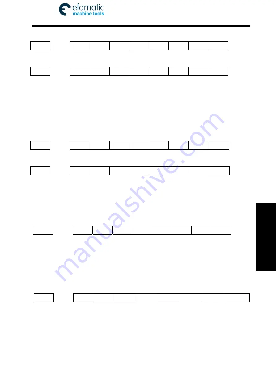
X0005
*** *** *** ***
*** *** *** SALM
SALM: spindle 1 abnormality alarm input
X0006
*** *** ×100 ×10 ×1 ZHAN
YHAN
XHAN
×100:
increment ×100
(
external
)
×10:
increment×10
(
external
)
×1:
increment×1
(
external
)
ZHAN:
Z selection
(
external
)
YHAN:
Y selection
(
external
)
XHAN:
X selection
(
external
)
X0008
*** *** *** *** *** *** ***
SALM2
SALM2: the alarm input signal of second spindle
X0009
*** *** *** ***
EXESP
*** SP ST
EXESP: External emergency stop input signal
SP: External pause
ST: External cycle start
5.2.2 Y Address (PLC
→
Machine, Defined by Standard PLC Ladders)
Y0000
SPZD
SCLP
M05 M04 M03 *** M32 COOL
SPZD: spindle brake
SCLP: spindle clamped
M05: spindle stop
M04: spindle rotation CCW
M03: spindle rotation CW
M32: lubricating output
COOL: cooling output
Y0001
TL- TL+ DOQPS DOQPJ S4/M44 S3/M43 S42/M42 S41/M41
TL-:
TL-tool post rotation (CW)
TL+:
TL+tool post rotation(CCW)
DOQPS: chuck release
DOQPJ:
chuck clamp
S4/M44:
spindle mechanical 4-gear
S3/M43:
spindle mechanical 3-gear
S2/M42:
spindle mechanical 2-gear
Содержание 980TDi
Страница 17: ...Official GSK Agents in South Africa Tel 27 11 626 2720 design efamatic com 1 Programming I Programming...
Страница 225: ...Official GSK Agents in South Africa Tel 27 11 626 2720 design efamatic com 209 Operation II Operation...
Страница 379: ...Official GSK Agents in South Africa Tel 27 11 626 2720 design efamatic com 363 Connection III Connection...
Страница 539: ...Official GSK Agents in South Africa Tel 27 11 626 2720 design efamatic com 523 IV Appendix IV Appendix...


