GE H
EALTHCARE
O
PTIMA
XR200
AMX
/XR220
AMX
D
IRECTION
5336113-1EN, R
EVISION
10
I
NSTALLATION
M
ANUAL
Page 112
Section 5.4 PACS image tests
Section 5.4 PACS image tests
PACS image tests apply only to Optima XR220amx or Optima XR200amx with digital upgrade
systems.
Follow these procedures to test image display characteristics and determine the burn configuration
for PACS images for each destination host.
5.4.1 Comparing PACS test images
In the following tests, use the nine PACS test images to test image display characteristics and
determine image display configuration.
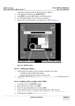
Each PACS test image consists of two aspects:
•
On the right, a clinical chest image with image number and GE logo watermark (
•
On the left, a series of 12 vertical bands. The top six bands are dark and the bottom six are
bright.
Inside each band are five small squares with different intensities (like the 5%/95% squares in
a SMPTE pattern). The squares provide a quantitative way to compare two images.
The pixel data in every test image is identical. Only the DICOM headers, annotations, and window
center (WC) and window width (WW) values are slightly different for each pattern.
Figure 5-1 PACS/image display test image
5.4.2 Determining PACS burn/no-burn configuration
5.4.2.1 Verifying PACS monitor calibration
1.
Verify that the PACS monitor is calibrated according to DICOM Standard Part 14. Each site is


