GE Multilin
F60 Feeder Protection System
C-9
APPENDIX C
C.4 GENERIC SUBSTATION EVENT SERVICES: GSSE AND GOOSE
C
Items programmed for dataset 1 and 2 will have changes in their status transmitted as soon as the change is detected.
Dataset 1 should be used for high-speed transmission of data that is required for applications such as transfer tripping,
blocking, and breaker fail initiate. At least one digital status value needs to be configured in dataset 1 to enable transmis-
sion of all data configured for dataset 1. Configuring analog data only to dataset 1 will not activate transmission.
Items programmed for datasets 3 through 8 will have changes in their status transmitted at a maximum rate of every
100 ms. Datasets 3 through 8 will regularly analyze each data item configured within them every 100 ms to identify if any
changes have been made. If any changes in the data items are detected, these changes will be transmitted through a
GOOSE message. If there are no changes detected during this 100 ms period, no GOOSE message will be sent.
For all datasets 1 through 8, the integrity GOOSE message will still continue to be sent at the pre-configured rate even if no
changes in the data items are detected.
The GOOSE functionality was enhanced to prevent the relay from flooding a communications network with GOOSE mes-
sages due to an oscillation being created that is triggering a message.
The F60 has the ability of detecting if a data item in one of the GOOSE datasets is erroneously oscillating. This can be
caused by events such as errors in logic programming, inputs improperly being asserted and de-asserted, or failed station
components. If erroneously oscillation is detected, the F60 will stop sending GOOSE messages from the dataset for a min-
imum period of one second. Should the oscillation persist after the one second time-out period, the F60 will continue to
block transmission of the dataset. The F60 will assert the
MAINTENANCE ALERT: GGIO Ind XXX oscill
self-test error mes-
sage on the front panel display, where
XXX
denotes the data item detected as oscillating.
The configurable GOOSE feature is recommended for applications that require GOOSE data transfer between UR-series
IEDs and devices from other manufacturers. Fixed GOOSE is recommended for applications that require GOOSE data
transfer between UR-series IEDs.
IEC 61850 GOOSE messaging contains a number of configurable parameters, all of which must be correct to achieve the
successful transfer of data. It is critical that the configured datasets at the transmission and reception devices are an exact
match in terms of data structure, and that the GOOSE addresses and name strings match exactly. Manual configuration is
possible, but third-party substation configuration software may be used to automate the process. The EnerVista UR Set-
upsoftware can produce IEC 61850 ICD files and import IEC 61850 SCD files produced by a substation configurator (see
the IEC 61850 IED configuration information later in this appendix).
Use independent ports for IEC 61850 communication and take care when configuring the settings,
else loss of protection or misoperation of the relay can result.
The following example illustrates the configuration required to transfer IEC 61850 data items between two devices. The
general steps required for transmission configuration are:
1.
Configure the transmission dataset.
2.
Configure the GOOSE service settings.
3.
Configure the data.
The general steps required for reception configuration are:
1.
Configure the reception dataset.
2.
Configure the GOOSE service settings.
3.
Configure the data.
This example shows how to configure the transmission and reception of three IEC 61850 data items: a single point status
value, its associated quality flags, and a floating point analog value.
The following procedure illustrates the transmission configuration.
1.
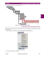
Configure the transmission dataset by making the following changes in the
PRODUCT SETUP
COMMUNICATION
IEC 61850 PROTOCOL
GSSE/GOOSE CONFIGURATION
TRANSMISSION
CONFIGURABLE GOOSE
CONFIGURABLE
GOOSE 1
CONFIG GSE 1 DATASET ITEMS
settings menu:
–
Set
ITEM 1
to “GGIO1.ST.Ind1.q” to indicate quality flags for GGIO1 status indication 1.
–
Set
ITEM 2
to “GGIO1.ST.Ind1.stVal” to indicate the status value for GGIO1 status indication 1.
The transmission dataset now contains a set of quality flags and a single point status Boolean value. The reception
dataset on the receiving device must exactly match this structure.
NOTICE
Содержание F60
Страница 10: ...x F60 Feeder Protection System GE Multilin TABLE OF CONTENTS ...
Страница 30: ...1 20 F60 Feeder Protection System GE Multilin 1 5 USING THE RELAY 1 GETTING STARTED 1 ...
Страница 138: ...4 28 F60 Feeder Protection System GE Multilin 4 2 FACEPLATE INTERFACE 4 HUMAN INTERFACES 4 ...
Страница 454: ...5 316 F60 Feeder Protection System GE Multilin 5 10 TESTING 5 SETTINGS 5 ...
Страница 500: ...7 14 F60 Feeder Protection System GE Multilin 7 1 COMMANDS 7 COMMANDS AND TARGETS 7 ...
Страница 508: ...8 8 F60 Feeder Protection System GE Multilin 8 2 FAULT LOCATOR 8 THEORY OF OPERATION 8 ...
Страница 522: ...10 12 F60 Feeder Protection System GE Multilin 10 6 DISPOSAL 10 MAINTENANCE 10 ...
Страница 660: ...B 116 F60 Feeder Protection System GE Multilin B 4 MEMORY MAPPING APPENDIX B B ...
Страница 706: ...E 10 F60 Feeder Protection System GE Multilin E 1 IEC 60870 5 104 APPENDIX E E ...
Страница 718: ...F 12 F60 Feeder Protection System GE Multilin F 2 DNP POINT LISTS APPENDIX F F ...
Страница 728: ...H 8 F60 Feeder Protection System GE Multilin H 2 ABBREVIATIONS APPENDIX H H Z Impedance Zone ...
Страница 730: ...H 10 F60 Feeder Protection System GE Multilin H 3 WARRANTY APPENDIX H H ...


