Software Control:
xT microscope Control Software
4-15
Auto Beam Shift Zero
automatically resets the beam shift each time it reaches the maximal
value during the Get function (the point-to-point stage movement) and
corrects the image position with a stage movement.
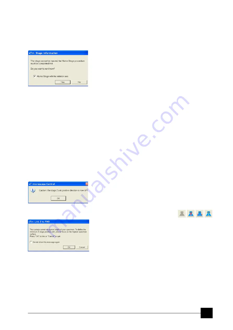
Home Stage (Shift + F3)
starts procedure which moves all motorized axes to their hardware
limits and ensures that the physical stage position agrees with the
coordinates readout. During the home stage procedure the
xTm:
Stage Information
dialogue displays its progress. The stage axes are
moved to their end-switches in the following order:
1. Z
(to the lowest position),
2.
T
(tilt),
3.
X
,
Y
and
R
(rotation) at the
same time. When the stage is homed correctly it ends up in the
following position:
X
/
Y
position is set to the factory pre-set stage rotation centre,
R
= 0°,
T
= 0°,
Z
= preset long working distance (depends on the stage type).
Home Stage Without Rotation
executes Home Stage function (see above) without rotation. When the
stage is homed without rotation the stage Rotation reference is greyed
out. This is useful when a large specimen is inserted and stage
rotation could cause a collision with equipment inside the chamber.
Center Position (Ctrl + 0 - digit)
moves the stage to coordinates X = 0, Y = 0.
Touch Alarm Enabled
activates the Touch Alarm for the stage. This function automatically
stops the stage movement and displays Touch Alarm warning
dialogue whenever the stage or a conductive specimen touches the
objective lens or any other equipment conductively connected to the
chamber. This functionality is used also when the stage engines start
to rise the power over the determined level.
Unlink Z to FWD
This feature functions in an opposite way as the following one. The Z
coordinate value represents then the distance from the Z home
position (stage base). The dialogue warns you about the stage Z axis
positive move direction.
Link Z to FWD (Shift + F9)
sets the Z coordinate value to the actual
Free Working Distance (FWD) value. This allows accurate movement
between the sample top surface and the end of the objective lens. The
related toolbar icon changes according to the Z-coordinate status:
•
Greyed icon
: the function is disabled – the high voltage is switched
off (so there could be no electron image) or all quads are paused.
•
Red question mark
: the function is enabled – Z is not linked to
FWD. Use the function as soon as possible, after properly focusing
the image.
•
Red circle
: the function is enabled – Z is roughly linked to FWD,
but it needs correction. It happens e.g. after: changing the
specimen, focusing and linking Z to FWD at a long WD and then
moving the stage to a short WD. Focus image carefully at a WD
around 10 mm and use this function again.
•
Green double-ended arrow
: the function is enabled – Z is
properly linked to FWD. Now it should be safe to change the
working distance by setting a Z coordinate in the Stage module.
Содержание Quanta FEG 250
Страница 8: ...C vi...
Страница 28: ...System Operation Quanta FEG System States 3 10...
Страница 108: ...Alignments 1 Gun Alignment 6 6...
Страница 114: ...Alignments 154 Water Bottle Venting 6 12 154 Water Bottle Venting...
Страница 152: ...System Options Automatic Aperture System 9 4...
Страница 154: ...System Options Nav Cam 9 6 401 NAV CAM AUTOBRIGHTNESS...
Страница 177: ...System Options Cooling Stage Waterless Cooling Stage 9 29...


