Software Control:
Software Interface Elements
4-5
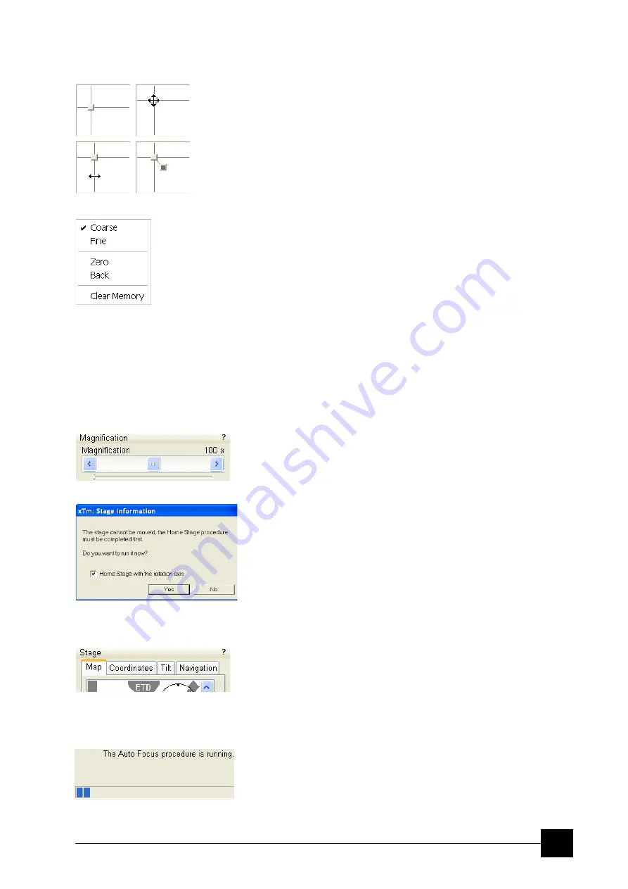
2D CONTROLS
are represented by an X-Y box. The position of the crosshair
corresponds to the actual parameter value with respect to its full range
being represented by the perimeter of the box.
Pressing anywhere inside the box changes the active quad cursor to
the four-ended arrow and positions it to the screen point corresponding
to the actual control value (minimum in the middle of the screen and
maximum at the edges). It can be moved in four directions. Pressing
directly on the X / Y axis changes the active quad cursor to the two-
ended arrow, which can be moved in the corresponding direction only.
To fix the values, release the mouse button.
The right-clicking over the 2D box opens a dialogue with choices:
•
The
Coarse
/
Fine
sets the mouse sensitivity – long / short mouse
path necessary for the full range.
•
The
Zero
brings the control value to zero and the cursor to the
center of the box.
•
The
Back
brings the control value one step back (only one step is
remembered).
•
The
Clear Memory
clears condition values, which have been
remembered automatically during the considered 2D control use.
These remembered values are used to estimate new values, which
have not been remembered yet.
The menu may contain less or some other functions that are actually
available for the particular parameter. Selecting the corresponding
menu item activates the function.
MODULES
visually combine various software elements, which are related into a
labeled group. Complex software elements like UI pages or dialogues
are typically composed of modules.
DIALOGUES
appear when the system needs more information from you before it
can carry out a command, or want to give you some important actual
information. Some dialogues do not let you access other functions
until you close them, other ones let you perform other tasks while they
remain onscreen and active (for example, the Preferences dialogue
can remain opened while performing other tasks).
TABS
In modules or dialogues containing more interface elements than
would fit into the limited area the
Tabs
are used. These related
elements are split into the groups (sections) and each one is
supplemented with the labeled Tab. Clicking the Tab brings it to the
foreground displaying the corresponding group of interface elements.
PROGRESS BARS
indicate progress of a long ongoing procedure over time. It is often
displayed in a dedicated dialogue.
Содержание Quanta FEG 250
Страница 8: ...C vi...
Страница 28: ...System Operation Quanta FEG System States 3 10...
Страница 108: ...Alignments 1 Gun Alignment 6 6...
Страница 114: ...Alignments 154 Water Bottle Venting 6 12 154 Water Bottle Venting...
Страница 152: ...System Options Automatic Aperture System 9 4...
Страница 154: ...System Options Nav Cam 9 6 401 NAV CAM AUTOBRIGHTNESS...
Страница 177: ...System Options Cooling Stage Waterless Cooling Stage 9 29...


