10
ENGLISH
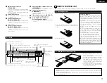
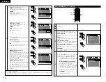
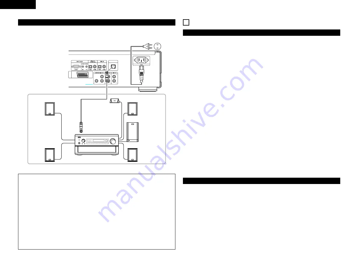
(8) Denon Link connections
High quality digital sound with reduced digital signal transfer loss can be enjoyed by connecting a separately
sold Denon Link compatible AV amplifier.
P
B
/C
B
P
R
/C
R
DENON LINK
AV1
PHONES
DIRECT
STEREO
ANALOG
EXT. IN
DOLBY
SURROUND
DTS
SURROUND
WIDE
SCREEN
CINEMA /
MUSIC
6.1 / 7.1
SURROUND
VIDEO
ON / OFF
STATUS
M-ZONE 1
FUNCTION
CONTROL
INPUT
MODE
5CH / 7CH
STEREO
DSP
SIMULATION
TONE
DEFEAT
MODE
SELECT
REC /
M-ZONE 2
SURROUND MODE
INPUT
REC SELECT / M-ZONE
MULTI FUNCTION
DVD-A1
To power outlet
Front speaker (left)
Surround speaker (left)
DENON LINK
AV amplifier with Denon Link input
terminals
Surround speaker (right)
Subwoofer
Front speaker (right)
Center speaker
NOTES:
• With Denon Link, digital transfer is only possible for discs that are not copyright-protected.
• When playing linear PCM or packed PCM DVDs that are not copyright-protected, digital transfer is possible
at up to 24-bits/2-channels for 192/176.4 kHz or 24-bits/6-channels for 96 kHz by using Denon Link
connections.
• When playing copyright-protected linear PCM or packed PCM DVDs, in consideration of copyrights, linear
PCM signals are not output from the DENON LINK terminal for sources exceeding 48 kHz/16 bits, so also
make analog connections (see page 9). “PROTECTION” is displayed on the DVD-A1’s display when
copyright-protected DVDs are played.
• To output signals from the DENON LINK terminal when playing DVDs that are not copyright-protected, set
“DIGITAL OUTPUT” at “PURE DIRECT MODE” to “OFF”. (See page 29.)
(If set to “ON”, for some discs signals below 96 kHz/2 channels will be output from the DENON LINK and
analog audio output terminals.)
• Set “LPCM (44.1 kHz/48 kHz)” under “AUDIO SETUP” at “SETUP” to “OFF”. (See page 18.)
(If set to “ON”, analog audio signals converted to 48 kHz will be output for linear PCM or packed PCM
sources.)
• To output the bitstream signals of Dolby Digital, DTS or other sources from the DENON LINK terminals,
set “DIGITAL OUTPUT” at “PURE DIRECT MODE” to “ON”. (See page 29.)
• The DVD-A1’s speaker settings are invalidated when Denon Link connections are used.
5
PART NAMES AND FUNCTIONS
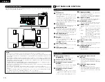
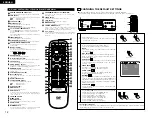
(1) Front Panel
See page 3.
q
Power button
• Press once to turn the power on.
• Press again to set to the “OFF” position and
turn the power off.
• Set the power to the standby mode by
pressing the POWER OFF button on the
remote control unit while the power is on.
• Turn the power on from the standby mode by
pressing the POWER ON button on the
remote control unit.
w
Power indicator
• This indicator lights when the power is on and
when the power is in the standby mode.
e
AL24 PLUS indicator
•
This indicator lights when the audio signals of
a DVD, etc., are being processed digitally with
the AL24 Processing Plus, a newly developed
analog waveform reproduction technology.
r
DVD AUDIO indicator
• This indicator lights when playing discs
recorded in DVD audio format.
t
Disc tray
• Load discs here. (See page 22.)
• Press the OPEN/CLOSE button
!4
to open
and close the disc tray.
• The disc tray is also closed when the PLAY
button
y
is pressed.
y
PLAY button (PLAY)
• Press this button to play the disc. (See page
23.)
u
STOP button (STOP)
• Press this to stop the disc. (See page 23.)
i
Skip button (
8
)
• Press this to move back to the beginning of
the current track (or chapter).
• Press again to move back to the beginning of
the previous track (or chapter). (See page 24.)
o
Skip button (
9
)
•
Press this to move ahead to the beginning of
the next track (or chapter). (See page 24.)
!0
PURE DIRECT selector
•
Use this to select modes with specific movie
signal and digital audio signal output settings.)
!1
SOURCE selector
• Use this to select the program source for
output.
DVD
: The signals of the disc being
played on the DVD-A1 are output.
OPTICAL
: The program source connected to
the OPTICAL digital input
connector is output.
COAXIAL
: The program source connected to
the COAXIAL digital input
connector is output.
• The program source selected with this
selector is also output to the digital output
connector.
!2
Remote control sensor
!3
Display
• Information on the disc that is currently playing
is shown on the display. (See page 11.)
!4
OPEN/CLOSE button
(
5
OPEN/CLOSE)
• Press this button to open and close the disc
tray.(See page 22.)
(2) Rear Panel
!5
Audio output connectors
(AUDIO OUT)
• Connect using the included audio cord.
!6
Control connector (RS-232C)
• This is a terminal for future system expansion.
!7
Digital audio output connector
(OPTICAL)
•
Connect using an optical fiber cable (available
in stores).
•
Digital data is output from this connector.
!8
Digital audio output connector
(COAXIAL)
• Connect using an audio cord. Connect a
commercially available 75
Ω
/ohms pin-plug
cord.
• Connect using the included audio video cord.
!9
Digital audio input connector
(OPTICAL)
• Input digital data to this connector.
• Connect the OPTICAL digital output connector
of a CD player, DAT deck, MD recorder, etc.,
to this connector to monitor the sound of that
component.
@0
Digital audio input connector
(COAXIAL)
• Input digital data to this connector.
• Connect the COAXIAL digital output connector
of a CD player, DAT deck, MD recorder, etc.,
to this connector to monitor the sound of that
component.

