Engström Carestation
9-22
08/07 1505-1018-000
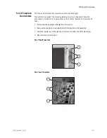
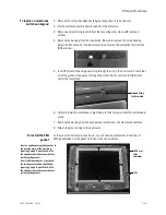
9.5.4 To replace
the CPU board
1. Remove the
connector panel assembly
(21) — two screws.
2. Disconnect the following cables:
• Inverter harnesses (
A
)
• Right membrane switch flex-cable at ZIF (zero insertion force) connector (
B
)
• Speaker cable (
C
)
• Encoder assembly cable (
D
)
• Lower membrane switch flex-cable at ZIF (zero insertion force) connector (
E
)
• Fan cable (
F
)
• LCD cable (
G
) Make sure cable is plugged in securely, if not screen may display
incorrectly (white).
• Left membrane switch flex-cable at ZIF (zero insertion force) connector (
H
)
3. Remove the remaining four screws (
I
) that hold the CPU board to the mounting plate.
4. Remove the CPU board from the mounting plate.
5. Transfer the battery (5) to the new CPU board.
6. Reassemble in reverse order.
7. Download the latest software (Section 8.4).
B
I
C
D
F
G
(21)
I
(5)
I
I
A
E
H
Содержание Engstrom Carestation
Страница 1: ...Engström Carestation Technical Reference Manual ...
Страница 12: ...Engström Carestation x 08 07 1505 1018 000 ...
Страница 52: ...Engström Carestation 2 26 08 07 1505 1018 000 ...
Страница 100: ...Engström Carestation 5 26 08 07 1505 1018 000 ...
Страница 124: ...Engström Carestation 7 16 08 07 1505 1018 000 ...
Страница 188: ...Engström Carestation 8 26 08 07 1505 1018 000 ...
Страница 225: ...ERROR undefined OFFENDING COMMAND STACK ...


