7-10
Cisco Network Modules Hardware Installation Guide
OL-2485-20
Chapter 7 Connecting ISDN PRI Network Modules
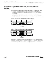
Channelized E1/ISDN PRI Balanced (120-Ohm) Network Modules
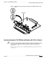
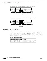
CE1/PRI Module Jumper Settings
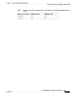
Jumpers on CE1/PRI modules can be used to connect or disconnect receive shield to ground. (See
Table 7-2
.) The default setting for balanced, 120-ohm CE1/PRI-B modules disconnects receive shield to
ground. The default setting for unbalanced, 75-ohm CE1/PRI-U modules connects receive shield to
ground. If you are experiencing ground loop problems with E1 cabling, you may want to try changing
the jumper settings for the module.
Connecting CE1/PRI-B Modules to the Network
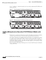
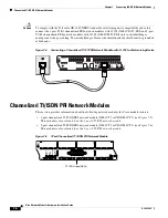
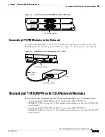
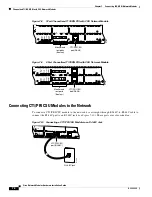
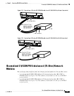
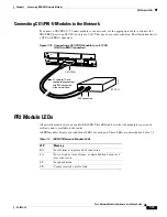
To connect a CE1/PRI-B (120-ohm) module to the network, use the appropriate cable to connect the
CE1/PRI-B port to an E1 CSU. (See
Figure 7-13
,
Figure 7-14
, and
Figure 7-15
, showing DB-15, twinax,
and RJ-45 CSUs, respectively.) These ports are color-coded tan.
Figure 7-13 Connecting a 120-ohm CE1/PRI-B Module to an E1 CSU (DB-15-to-DB-15 Connectors)
Table 7-2
CE1/PRI Module Jumpers
CE1/PRI Module Type Default Setting
Function
Balanced, 120-ohm
2 and 3
Disconnects receive shield from ground
Unbalanced, 75-ohm 1 and 2
Connects receive shield to ground
LOOP
BACK
EN
FE-PRI
1FE-1CE1-B/U
LOCAL
ALARM
REMOTE
ALARM
CARRIER
DETECT
10/100BaseT
COLL
LINK
100Mbps
FDX
H7470
CE1/PRI-B (DB-15)
DB-15 connector
E1 CSU
E1 cable for 120-ohm
balanced connections
with a DB-15 connector
at the network end
CTRLR 0


