17-10
Cisco Network Modules Hardware Installation Guide
OL-2485-20
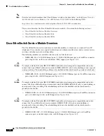
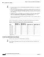
Chapter 17 Connecting Ethernet Switch Network Modules
Ethernet Switch Network Module LEDs
Ethernet Switch Network Module LEDs
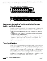
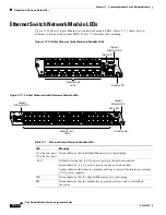
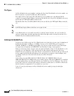
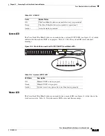
Figure 17-10
shows 16-port Ethernet switch network module LEDs.
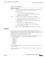
Figure 17-11
shows 36-port
Ethernet switch network module LEDs.
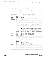
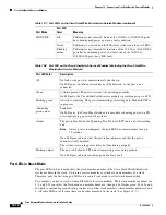
Table 17-1
describes their meaning.
Figure 17-10 16-Port Ethernet Switch Network Module LEDs
Figure 17-11 36-Port Ethernet Switch Network Module LEDs
Table 17-1
Ethernet Switch Network Module LEDs
LED
Meaning
0–16 (for 16-port)
0–36 (for 36-port)
Green indicates that individual Ethernet port is functioning.
–48-V
Off indicates that no –48-V power is going to the network module.
Green indicates –48-V power is present on the network module.
Amber indicates that there is a problem with one or more of the internal or external
–48-V power supplies.
GE
Green indicates that the Gigabit Ethernet port is functioning.
EN
Green indicates that the module has passed its self-tests and is available to
the router.
EN
NM-
ESW-
16
62586
15x 7x
14x
6x
13x
5x
FastEthernet Ports
12x
4x
11x 3x
10x
2x
9x
1x
8x
0x
Ext
Pwr
-48V
0x
8x
7x
15x
GE
10/100/
1000
Base-Tx
Ethernet port
LEDs
Enable LED
-48V LED
Gigabit
Ethernet LED
EN
NMD-
ESW-
36
72005
23x
5x
FastEthernet Ports
22x
4x
21x 3x
20x
2x
19x
1x
18x
0x
29x 11x
28x 10x
27x 9x
26x
8x
25x
17
24x
6x
35x 17x
34x 16x
33x 15x
32x 14x
31x 13x
30x 12x
Ext
Pwr
-48V
0x
18x
GE0
10/100/
1000
Base-Tx
35x
10/100/1000
Base-Tx
GE1
17x
Ethernet port
LEDs
Enable LED
-48V LED
Gigabit
Ethernet LED
Gigabit
Ethernet LED


