16-2
Cisco Network Modules Hardware Installation Guide
OL-2485-20
Chapter 16 Connecting High-Density Analog Telephony Network Modules
High-Density Analog Telephony Network Module
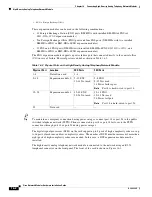
These expansion modules can be used in the following combinations:
•
12 Foreign Exchange Station (FXS) ports (NM-HDA with installed EM-HDA-8FXS
and
EM3-HDA-8FXS
expansion module
s
)
•
Ten Foreign Exchange Office (FXO) ports and four FXS ports (NM-HDA with two installed
EM-HDA-4FXO or EM2-HDA-4FXO expansion modules)
•
12 FXS and 4 FXO ports (NM-HDA with installed EM-HDA-8FXS
, EM3-HDA-8FXS,
and
EM-HDA-4FXO or EM2-HDA-4FXO expansion modules)
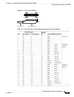
The FXO expansion module supports a power failure port that connects directly to the central office
(CO) in case of failure. Physical ports are added as shown in
Table 16-2
.
Tip
To maintain an emergency connection during power outages, connect port 14 or port 24 to the public
switched telephone network (PSTN). Phones connected to port 8 or port 18 fail over to the PSTN
connections through port 14 or port 24 during power outages.
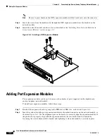
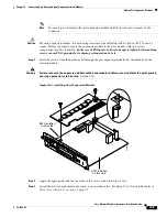
The digital signal processors (DSPs) on the card support up to 8 ports of high-complexity codecs or up
to 16 ports of medium- and low-complexity codecs. The number of DSPs must be increased if more than
eight ports of high-complexity codecs are needed. In this case, a DSP expansion module must be
installed.
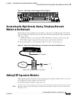
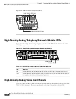
The high-density analog telephony network module is connected to the network using an RJ-21
Amphenol connector on the front panel. The front of the card is shown in
Figure 16-1
.
1.
FXO = Foreign Exchange Office
Table 16-2 Physical Ports on the High-Density Analog Telephony Network Module
Physical Port
Location
FXS Ports
FXO Ports
1–4
Default on card
1–4
—
5–14
Expansion module 0
5–12 FXS
13–14 Not used
5–8 FXO
9–13 Not used
14 Power failure port
Note
Port 8 is hard-wired to port 14.
15–24
Expansion module 1
15–22 FXS
23–24 Not used
15–18 FXO
19–23 Not used
24 Power fail port
Note
Port 18 is hard-wired to port 24.
25
Not used
—
—

