28-9
Cisco Network Modules Hardware Installation Guide
OL-2485-20
Chapter 28 Connecting Cisco High-Density Extension Modules
Cisco High-Density Extension Module Cable Pinouts
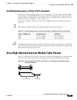
Establishing Emergency or Power-Fail Connections
During power failures or when router power is off, emergency voice connections can be made through
power-fail ports on the EM-HDA-6FXO expansion module. The expansion module must be properly
installed on the Cisco high-density extension module. (See the
“Installing Expansion Modules on Cisco
High-Density Extension Modules” section on page 28-4
.)
To provide an emergency connection, connect an analog phone using the port information listed in
Table 28-3
.
Note
There will not be a dial tone on port 15 or port 23 until the router is powered down.
Caution
Analog phones connected to the power-fail ports should not be connected in parallel to a normal FXS
port on Cisco high-density extension modules. The protection circuit on the FXS port can interfere with
phone operation when router power is off.
Cisco High-Density Extension Module Cable Pinouts
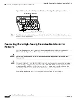
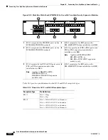
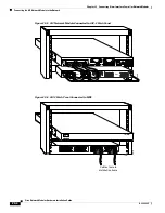
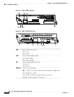
Figure 28-6
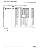
shows the RJ-21 connector wiring for the cable used for the high-density extension module,
and
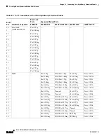
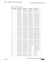
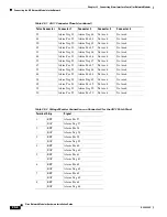
Table 28-4
lists cable pinouts. Port usage depends on the type of installed expansion module.
Figure 28-6 Close-Up of the RJ-21 Connector Pinout for Cisco High-Density Extension Modules
(EVM-HD-8FXS/DID)
Table 28-3 Establishing Emergency Connections through Cisco High-Density Extension Modules
Expansion Module Slot
Analog Phone Port
PSTN Port
EM0
Port 15 Tip/Ring
Port 13 Tip/Ring
EM1
Port 23 Tip/Ring
Port 21 Tip/Ring
103160
RJ-21 cable
RJ-21 connector
26
50
25
1


