28-11
Cisco Network Modules Hardware Installation Guide
OL-2485-20
Chapter 28 Connecting Cisco High-Density Extension Modules
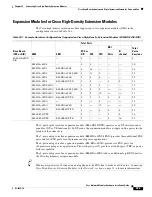
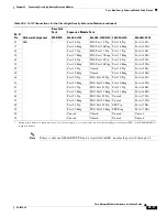
Cisco High-Density Extension Module Cable Pinouts
Note
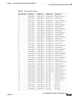
If there is only one EM-4BRI-NT/TE and it is installed in EM1, number the ports
x
/0 through
x
/3.
42
EM1
—
Port 16 Tip
FXS Port 16 Tip
Port 16 Tip
Port
x
/4 SX–
17
Port 16 Ring
FXS Port 16 Ring Port 16 Ring
Port
x
/4 SX+
43
Port 17 Tip
FXS Port 17 Tip
Port 17 Tip
Port
x
/4 SR-
18
Port 17 Ring
FXS Port 17 Ring Port 17 Ring
Port
x
/4 SR+
44
Port 18 Tip
FXS Port 18 Tip
Port 18 Tip
Port
x
/5 SX–
19
Port 18 Ring
FXS Port 18 Ring Port 18 Ring
Port
x
/5 SX+
45
Port 19 Tip
Unused
Port 19 Tip
Port
x
/5 SR-
20
Port 19 Ring
Unused
Port 19 Ring
Port
x
/5 SR+
46
Port 20 Tip
FXO Port 20 Tip
Port 20 Tip
Port
x
/6 SX–
21
Port 20 Ring
FXO Port 20 Ring Port 20 Ring
Port
x
/6 SX+
47
Port 21 Tip
FXO Port 21 Tip
Port 21 Tip
Port
x
/6 SR-
22
Port 21 Ring
FXO Port 21 Ring Port 21 Ring
Port
x
/6 SR+
48
Port 22 Tip
FXO Port 22 Tip
Unused
Port
x
/7 SX–
23
Port 22 Ring
FXO Port 22 Ring Unused
Port
x
/7 SX+
49
Port 23 Tip
FXO Port 23 Tip
PFP Tip
Port
x
/7 SR-
24
Port 23 Ring
FXO Port 23 Ring PFP Ring
Port
x
/7 SR+
50
Unused
Unused
Unused
Unused
25
Unused
Unused
Unused
Unused
1.
During power failures or when router power is off, emergency voice connections can be made through power-fail ports (PFP) on the EM-HDA-6FXO
expansion module.
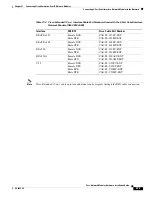
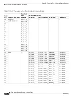
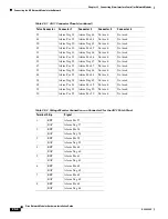
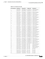
Table 28-4 RJ-21 Connections for the Cisco High-Density Extension Module (continued)
RJ-21
Pin
Hardware Component
Base Card
Ports
Expansion Module Ports
8FXS/DID
EM-HDA-8FXS
EM-HDA-3FXS/4FXO EM-HDA-6FXO
EM-4BRI-NT/TE

