39-11
Cisco Network Modules Hardware Installation Guide
OL-2485-20
Chapter 39 Connecting Cisco Analog Video Gateway Network Modules
How to Install, Connect, or Replace the EVM-IPVS-16A Network Module
Step 7
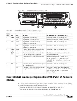
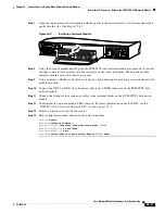
Align the replacement network module with the guides in the chassis walls or slot divider and slide it
gently into the slot. (See
Figure 39-8
.)
Figure 39-8
Installing a Network Module
Step 8
Using the network module handle, push the EVM-IPVS-16A network module into place until you feel
the edge connector seat securely into the connector on the router backplane. The network module
faceplate should contact the chassis rear panel.
Step 9
Using a number 1 Phillips or flat-blade screwdriver, tighten the captive mounting screws on the network
module faceplate.
Step 10
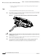
Connect the DB-37 to BNC video breakout cable to the VIDEO connector on the EVM-IPVS-16A
network module.
Step 11
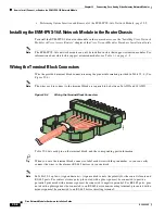
Connect the terminal block connector cables to the terminal blocks on the EVM-IPVS-16A network
module.
Step 12
Confirm that the network module LEDs come on. For more information about the LEDs, see the
“EVM-IPVS-16A Network Module LEDs” section on page 39-4
.
Step 13
Initiate a console session with your router.
Step 14
Enter configuration mode, and restart the network module:
Router>
enable
Router#
configure terminal
Router(config)#
interface video-Service-Engine
slot
/0
Router(config-if)#
no shutdown
Router(config-if)#
exit
Router#
service-module video-Service-Engine
slot
/0 reset
ETHERNET 0
WO
AC
T
SERIAL
230444
1
3210
11
20
EVM
IPVS-16A


