38-2
Cisco Network Modules Hardware Installation Guide
OL-2485-20
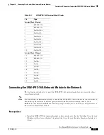
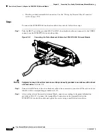
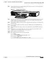
Chapter 38 Connecting 8-Port T1/E1 Network Modules
Cisco T1/E1 Network Module LEDs
Cisco T1/E1 Network Module LEDs
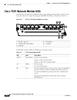
The T1/E1 network module has 2 LEDs for each port that indicate the functionality of the T1 or E1
connection.
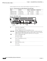
Figure 38-1
shows the front panel and LEDs. The LEDs are described in
Table 38-1
.
Figure 38-1
8-Port T1/E1 Network Module Front Panel
CD/LP LEDs are bicolor LEDs with both green and yellow emitters.
1
RJ-48C connector
2
Port number
3
CD/LP LED (bicolor LED)
4
AL LED
5
EN LED
NM-
8CE1T1-
PRI
170622
CD/LP P7 AL CD/LP P6 AL CD/LP P5 AL CD/LP P4 AL
CD/LP P3 AL CD/LP P2 AL CD/LP P1 AL CD/LP P0 AL
EN
3
4
2
5
1
Table 38-1
T1/E1 Network Module LEDs
LED
Color
Description
CD/LP
Green/Yellow
Off: No carrier detected
Green on (CD): Carrier detected
Yellow on (LP): Port in loopback mode
AL
Yellow
Off: No alarms
On: Port in alarm mode
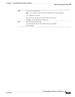
EN
Green
Off: Network module does not pass self-test and is not available to
the router. There is a failure with either the module or the slot.
On: Network module has passed self-test and is available to the
router.
The network module may be removed from router when the
EN LED is off.

