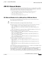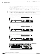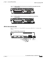
11-11
Cisco Network Modules Hardware Installation Guide
OL-2485-20
Chapter 11 Connecting ATM Network Modules
ATM OC-3 Network Modules
–
SFP-OC3-MM
•
Single-mode intermediate reach (SMI)
–
POM-OC3-SMIR
–
SFP-OC3-IR1
•
Single-mode long reach (SML)
–
POM-OC3-SMLR
–
SFP-OC3-LR1
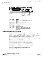
ATM-OC3-POM Network Module LEDs
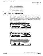
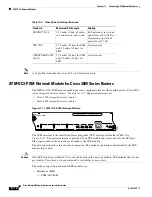
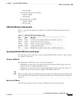
Table 11-7
describes the functions of the LEDs on the ATM-OC3-POM network module shown in
Figure 11-17
.
Connecting ATM-OC3-POM Ports to the Network
The following sections describe how to remove and install SFP modules, and how to connect the ports
on a module to the network.
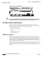
Handling an SFP Module
Before handling an SFP module, observe the following guidelines:
•
SFP modules are static-sensitive. To prevent electrostatic discharge (ESD) damage, follow your
normal board- and component-handling procedures.
•
SFP modules are dust-sensitive. When storing an SFP module or when a fiber-optics cable is not
plugged into the connector, always keep plugs in SFP module optical bores.
Note
The most common source of contaminants in the optical bores is debris picked up on the ferrules of the
optical connectors. Use alcohol swabs or lint-free absorbent wipes to clean the ferrules of the optical
connector.
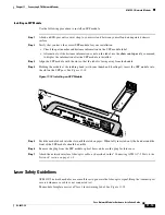
Removing an SFP Module
The following procedure describes removing an SFP module from the network module.
Table 11-7
ATM-OC3-POM Network Module LEDs
LED
Color
Meaning
RXCR
Green
Lit when carrier signal into the network module is present.
RXCL
Green
Blinks to indicate packet reception.
TXCL
Green
Blinks to indicate packet transmission.
RXALM
Yellow
Alarm indication signal.
EN
Green
Module has passed its self-tests and is available to the router.

