


UniVert User Manual
52
System Stiffness Compensation
System Stiffness Compensation can be used to compensate for the small displacements that
occur in the system during testing due to flexion and load cell compression/tension. These
displacements arise from any strains in the load cell and any bending or deformation of the
system during loading. Under most loading conditions, these displacements are negligible and
system stiffness compensation is not required. System stiffness compensation plays a more
significant role when testing stiff specimens that achieve high loads at low displacements.
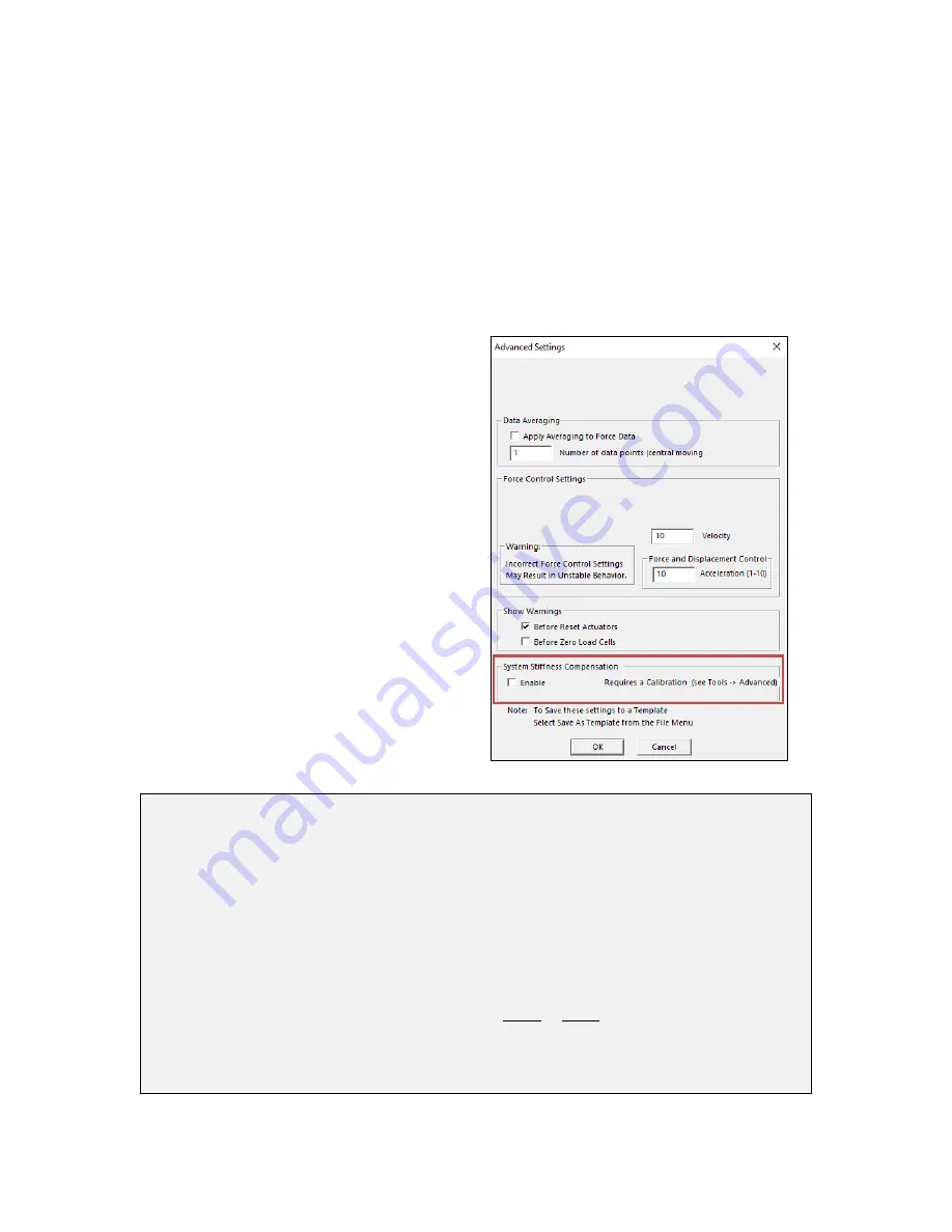
System Stiffness Compensation can be enabled or disabled under the Advanced Settings
dialogue (
Advanced
from the
Settings
menu).
When enabled, output displacement and size
data in the .csv data output file will be modified.
For example, in a test where a 10 mm specimen
is being compressed by 1mm at 100N of force
the system may be displacing by 0.1mm. In this
case when the actuators have moved 1 mm the
specimen will only have been deformed by 0.9
mm and the other 0.1 mm will have gone into
deforming the load cell and system. The output
will show a displacement of 0.9 mm (rather than
1.0) and a specimen size of 9.1 mm (rather than
9 mm).
Note:
The system stiffness compensation does
not affect or alter the applied loads or
displacements only the reported values in the
output .csv files.
The amount of compensation being applied to
the displacement and size columns of the output
data file can also be shown as an additional
output column (see the
Additional Settings
section).
UniVert Tip: When to Apply System Stiffness Compensation
Typically, System Stiffness Compensation will not be required. It may be useful, however,
when testing stiff specimens that achieve high loads at low displacements. Most of the
system deformation comes from the load cells which typically strain linearly by up to about
200
µ
m at full scale load. One can estimate the amount of system deformation by multiplying
200
µ
m by the percent of load cell range that is used. For example, when a load cell is at
50% of its full-scale load (a 200N load cell at 100N, or a 10N load cell at 5N) the system
deformation is estimated to be about 100
µ
m. To determine the effect of this displacement on
your test you can divide this estimated system deformation by the maximum displacement in
your test.
For example, in a test with 10mm of displacement:
100 𝑢𝑚
10 𝑚𝑚
=
0.1 𝑚𝑚
10 𝑚𝑚
= 1%
We recommend using system stiffness compensation if the system deformation is more than
10% of the applied deformation.
Содержание UniVert
Страница 1: ...UniVert Mechanical Test System User Manual version 3 0 ...
Страница 36: ...UniVert User Manual 31 ...
Страница 44: ...UniVert User Manual 39 Figure 6 Tracking Grid showing ID Numbers Figure 7 Sample Exported Data ...
Страница 78: ...UniVert User Manual 73 ...
Страница 79: ...UniVert User Manual 74 ...
Страница 80: ...UniVert User Manual 75 ...
Страница 81: ...UniVert User Manual 76 ...
Страница 82: ...UniVert User Manual 77 ...


