PTP 800 Series User Guide
Managing 1+ 1 Hot St andby links
phn- 2513_004v000 ( Oct 2012)
7- 35
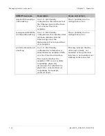
Sym bols or t e x t
M e a n in g
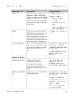
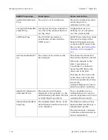
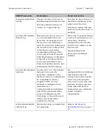
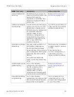
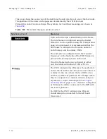
The CMU configured as Secondary will become
the inactive unit unless the Primary unit develops
a fault. In the case where the two ODUs at an end
have a different path loss, for example where they
are coupled to a common antenna using an
Asymmetric Coupler Mounting Kit (see
) , the CMU configured
as Secondary should be connected to the RFU
with the highest path loss.
For IRFUs, the CMU configured as Secondary
should always be connected to the right hand
transceiver.
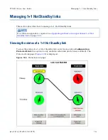
The IP address of the unit being browsed.
The IP address of the unit.
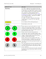
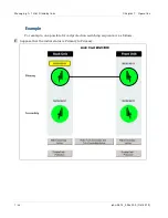
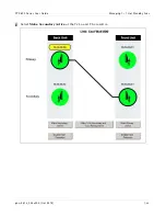
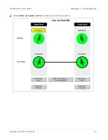
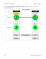
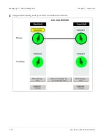
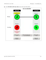
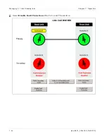
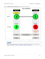
These units are active (Tx Hi and Tx Lo). Active
units are the units which radiate at the antenna
and forward traffic between the wireless interface
and the Ethernet ports. The black line represents
the link between active units.
These units are inactive (Tx Hi and Tx Lo).
Inactive units remain on standby waiting to take
over the active role in case of a fault. They do not
radiate or forward traffic between the Wireless
interface and the Ethernet ports.
These units are not protecting the active unit.
They may be faulty or configured in a way which
is not protecting the active unit. Roll the mouse
over the icon to see the reason why the unit is not
protecting.
The unit being browsed cannot communicate with
a unit identified in this way. This may be because
the unit is powered down or the protection cable
is not connected.
If both units at the end remote from the end being
managed are gray, this indicates that the wireless
link is down.
Содержание PTP 800 Series
Страница 1: ...Cambium PTP 800 Series User Guide System Release 800 05 02 ...
Страница 40: ...Licensing requirements About This User Guide 10 phn 2513_004v000 Oct 2012 ...
Страница 232: ...Limit of liability Chapter 3 Legal information 3 22 phn 2513_004v000 Oct 2012 ...
Страница 322: ...Radiation hazard assessm ent Chapter 4 Reference information 4 90 phn 2513_004v000 Oct 2012 ...
Страница 418: ...Replacing IRFU components Chapter 5 Installation 5 96 phn 2513_004v000 Oct 2012 Figure 1 1 0 IRFU components example ...
Страница 428: ...Replacing IRFU components Chapter 5 Installation 5 106 phn 2513_004v000 Oct 2012 ...
Страница 552: ...Configuring for FIPS 140 2 applications Chapter 6 Configuration and alignment 6 124 phn 2513_004v000 Oct 2012 ...
Страница 630: ...Using recovery mode Chapter 7 Operation 7 78 phn 2513_004v000 Oct 2012 ...
Страница 648: ...Glossary I V phn 2513_004v000 Oct 2012 ...

