PTP 800 Series User Guide
Replacing I RFU com ponent s
phn- 2513_004v000 ( Oct 2012)
5- 99
4
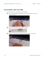
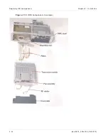
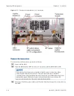
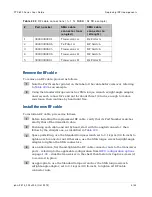
Remove the IRFU section Cover Plate
by unfastening both its Captive
thumbscrews.
5
Disconnect all RF cables from the transceiver, and the RF switch ribbon cable (not
present in 1+0 configurations)
from the bottom of the transceiver.
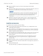
To reduce replacement time, it may be more practical to disconnect only the
end of each cable from the transceiver, and leave all cables within the shelf,
provided they do not interfere with the removal and installation of the
transceiver.
6
Unfasten the transceiver captive Captive screws (2), then carefully slide the
Transceiver module out of the shelf. It might be necessary to slightly raise the
transceiver in the front as it is being slid out.
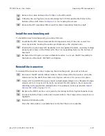
Install the new transceiver
To install the new transceiver, proceed as follows:
1
Connect the RF switch ribbon cable
(not present in 1+0 configurations)
to the
bottom of the new transceiver.
2
Space permitting, use the Standard torque wrench
set to 0.1 kg-m (9.0 lb-inch) to
tighten each connector nut. Otherwise, use the SMA torque wrench w/right-angle
adaptor to tighten the SMA connectors.
3
As an alternative, first hand-tighten the RF cable connector nuts to the transceiver
ports, slide the transceiver in the shelf, then fasten its Captive screws (2) to
secure it in place.
4
As appropriate, use the Standard torque wrench or the SMA torque wrench
w/right-angle adaptor,
set to 0.1 kg•m (9.
0 lb-inch), to tighten all RF cable
connector nuts.
5
Replace the IRFU section cover plate by fastening both its Captive thumbscrews.
6
Connect both the Power cable and Coaxial
cable to their respective connectors on
the IRFU.
7
Push the PWR button ON.
Once the radio link is re-established, verify that there are no alarms.
Содержание PTP 800 Series
Страница 1: ...Cambium PTP 800 Series User Guide System Release 800 05 02 ...
Страница 40: ...Licensing requirements About This User Guide 10 phn 2513_004v000 Oct 2012 ...
Страница 232: ...Limit of liability Chapter 3 Legal information 3 22 phn 2513_004v000 Oct 2012 ...
Страница 322: ...Radiation hazard assessm ent Chapter 4 Reference information 4 90 phn 2513_004v000 Oct 2012 ...
Страница 418: ...Replacing IRFU components Chapter 5 Installation 5 96 phn 2513_004v000 Oct 2012 Figure 1 1 0 IRFU components example ...
Страница 428: ...Replacing IRFU components Chapter 5 Installation 5 106 phn 2513_004v000 Oct 2012 ...
Страница 552: ...Configuring for FIPS 140 2 applications Chapter 6 Configuration and alignment 6 124 phn 2513_004v000 Oct 2012 ...
Страница 630: ...Using recovery mode Chapter 7 Operation 7 78 phn 2513_004v000 Oct 2012 ...
Страница 648: ...Glossary I V phn 2513_004v000 Oct 2012 ...

