PTP 800 Series User Guide
Task 6: Configuring prot ect ion
phn- 2513_004v000 ( Oct 2012)
6- 59
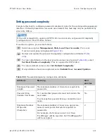
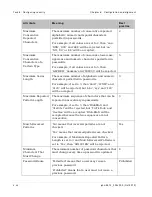
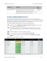
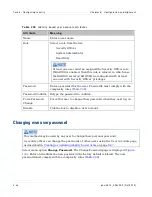
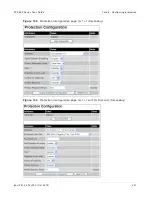
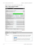
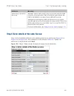
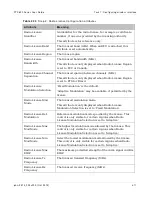
At t r ibu t e
M e a n in g
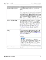
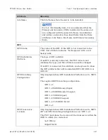
Fault Protection Switching
‘Enabled’ means that normal 1+1 operation is in
force.
‘Disabled’ means that a protection switch will not
occur when a fault is detected on the active unit. With
this setting, the user still has the ability to change
which unit is active. This setting can be useful during
installation or maintenance operations where the user
wishes to have full control of which unit is active.
When this is set to ‘Enabled’, a protection switch will
occur when a fault is detected on the active unit.
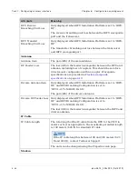
Primary Secondary mode
The CMU is configured as a Primary or Secondary.
The Primary is the preferred unit, meaning that it is
the active unit unless it is faulty. If the two ODUs at
an end have a different path loss, for example where
they are coupled to a common antenna using an
Asymmetric Coupler Mounting Kit (see
), connect the CMU
configured as Primary to the RFU with the lowest
path loss.
Fiber-Y
‘Enabled’ means that the neighboring CMUs at the
end of a 1+1 Hot Standby link are connected to the
network via a Fiber-Y interface (see
‘Disabled’ means that a Fiber-Y interface is not
installed.
If a CMU is being replaced in an otherwise
working 1+1 Hot Standby link, do not connect the
Fiber-Y cable to the CMU until this attribute is
enabled. If the Fiber-Y cable is connected before
enabling this attribute, the 1+1 link will not
transmit customer data.
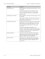
Number of Antennas
The number of antennas to be installed at this end of
the link.
Содержание PTP 800 Series
Страница 1: ...Cambium PTP 800 Series User Guide System Release 800 05 02 ...
Страница 40: ...Licensing requirements About This User Guide 10 phn 2513_004v000 Oct 2012 ...
Страница 232: ...Limit of liability Chapter 3 Legal information 3 22 phn 2513_004v000 Oct 2012 ...
Страница 322: ...Radiation hazard assessm ent Chapter 4 Reference information 4 90 phn 2513_004v000 Oct 2012 ...
Страница 418: ...Replacing IRFU components Chapter 5 Installation 5 96 phn 2513_004v000 Oct 2012 Figure 1 1 0 IRFU components example ...
Страница 428: ...Replacing IRFU components Chapter 5 Installation 5 106 phn 2513_004v000 Oct 2012 ...
Страница 552: ...Configuring for FIPS 140 2 applications Chapter 6 Configuration and alignment 6 124 phn 2513_004v000 Oct 2012 ...
Страница 630: ...Using recovery mode Chapter 7 Operation 7 78 phn 2513_004v000 Oct 2012 ...
Страница 648: ...Glossary I V phn 2513_004v000 Oct 2012 ...

