


12.9.6 PID Deactivation by Digital Input
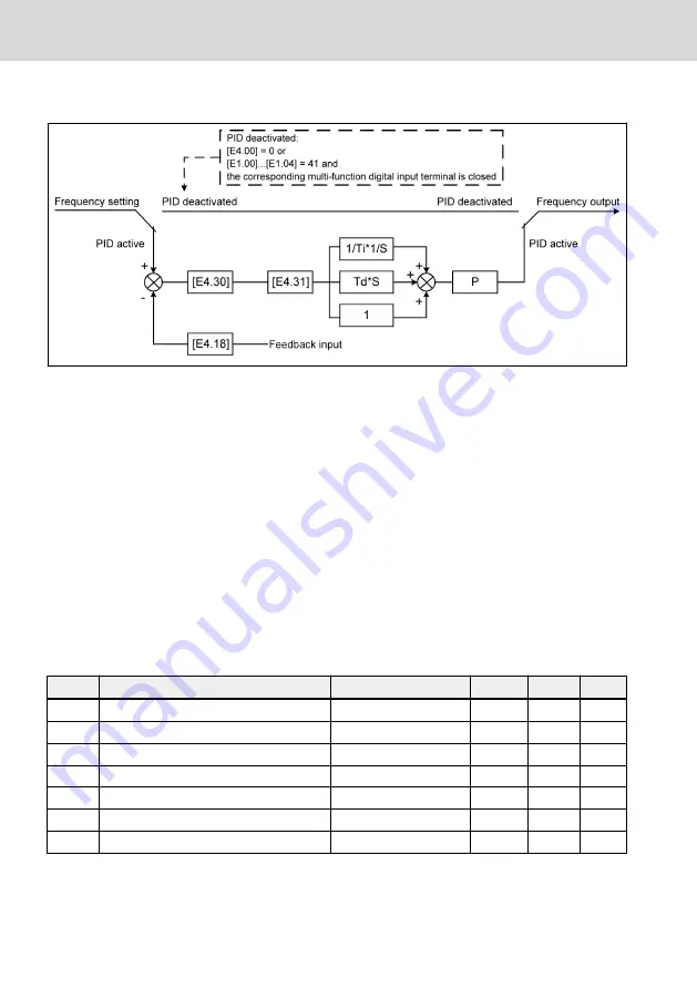
Fig. 12-39: PID deactivation by digital input
The PID control is deactivated in the following ways:
●
'PID reference channel' [E4.00] = '0: No PID control' or
●
[E1.00]...[E1.04] / [H8.00]...[H8.03] = '41: PID deactivation' and respective
multi-function digital input terminal is active.
12.9.7 PID Engineering Value Display
This function is used to display an engineering value which is convenient for the
application engineering with scaling the output value, follow the equations be-
low:
●
User-defined setting speed:
[d0.04] = [d0.02] x [E5.02]
●
User-defined actual speed:
[d0.05] = [d0.00] x [E5.02]
Code
Name
Setting range
Default
Min.
Attri.
E5.02 User-defined speed scaling factor
0.01...100.00
1.00
0.01
Run
d0.01 Actual speed
–
–
1 rpm Read
d0.03 Setting speed
–
–
1 rpm Read
d0.04 User-defined setting speed
–
–
0.1
Read
d0.05 User-defined output speed
–
–
0.1
Read
d0.70 PID reference engineering value
–
–
0.1
Read
d0.71 PID feedback engineering value
–
–
0.1
Read
[d0.70] = [E4.02] x [PID reference]
[d0.71] = [E4.02] x [PID feedback]
Bosch Rexroth AG
Functions and Parameters
VFC 3210
144/253
DOK-RCON04-VFC3210****-IT01-EN-P
Содержание Rexroth VFC 3210
Страница 1: ...Frequency Converter VFC 3210 Operating Instructions R912007862 Edition 01 ...
Страница 18: ...Bosch Rexroth AG VFC 3210 XVI DOK RCON04 VFC3210 IT01 EN P ...
Страница 146: ...Fig 12 23 Stop DC braking Bosch Rexroth AG Functions and Parameters VFC 3210 118 253 DOK RCON04 VFC3210 IT01 EN P ...
Страница 239: ...Fig 15 2 0020 N 03 0025 N 03 VFC 3210 Bosch Rexroth AG Accessories DOK RCON04 VFC3210 IT01 EN P 211 253 ...
Страница 240: ...Fig 15 3 0008 A 05 Fig 15 4 0020 N 05 Bosch Rexroth AG Accessories VFC 3210 212 253 DOK RCON04 VFC3210 IT01 EN P ...
Страница 249: ...Fig 16 3 Assembly of the fan VFC 3210 Bosch Rexroth AG Maintenance DOK RCON04 VFC3210 IT01 EN P 221 253 ...
Страница 280: ...Bosch Rexroth AG VFC 3210 252 253 DOK RCON04 VFC3210 IT01 EN P ...
Страница 281: ...Notes VFC 3210 Bosch Rexroth AG ...